How to Inspect High-Speed Backplane Headers with Stubbed Pins Using AI-Powered Vision
"High-speed backplane headers with stubbed pins require micron-level precision inspection that human operators cannot deliver consistently. Overview.ai's machine vision platform automates detection of stub length variations, burrs, bent pins, and plating defects at full production speed—eliminating the 15% escape rates common with manual inspection."
The Problem: Why Stubbed Pin Headers Are Notoriously Difficult to Inspect
High-speed backplane headers feature dozens or even hundreds of precisely machined stubbed pins designed to minimize signal reflection and impedance discontinuities. The stubbing process—where pin lengths are carefully trimmed to reduce via stubs—introduces multiple potential failure points that compromise performance in systems running at 25+ Gbps.
Common defects in stubbed pin headers include:
- Inconsistent stub length — Pins trimmed outside ±0.05mm tolerance cause impedance mismatches
- Burrs and metal debris — Residual material from the stubbing process creates short-circuit risks
- Bent or misaligned pins — Deflected pins fail to mate properly with daughter cards
- Plating defects — Insufficient or uneven gold plating leads to contact resistance issues
- Housing cracks — Stress fractures in the plastic body compromise mechanical integrity
- Coplanarity violations — Uneven pin heights prevent reliable surface-mount connections
Manual inspection simply cannot keep pace with modern production demands. Human inspectors experience fatigue after just 20-30 minutes of examining these repetitive, densely-packed components, leading to escape rates as high as 15% on critical defects.
The Solution: Machine Vision + Deep Learning
AI-powered visual inspection eliminates the variability inherent in human inspection. Deep learning models trained on thousands of header images learn to recognize subtle defect patterns that even experienced operators miss—including variations in stub length measured in microns.
Overview.ai's approach delivers consistent, objective inspection at full line speed. The OV80i system examines every single header without fatigue, maintaining the same detection accuracy on unit 10,000 as on unit 1.
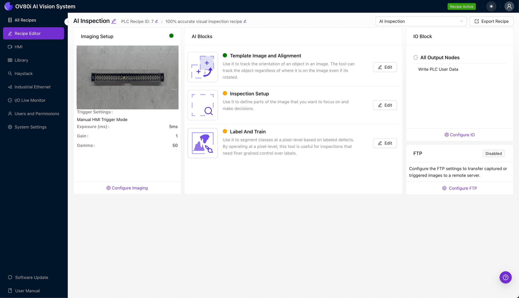
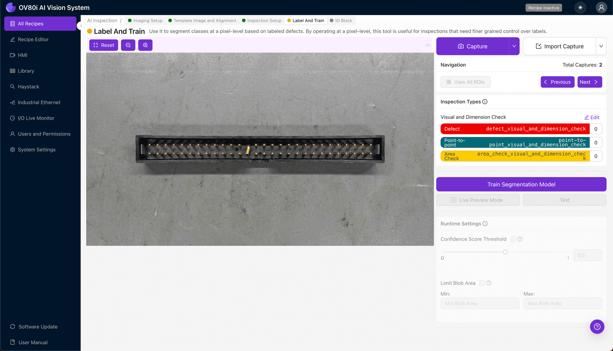
Step 1: Imaging Setup
Position the high-speed backplane header under the OV80i camera, ensuring the stubbed pins face upward for optimal visibility. Angled lighting often works best to highlight stub length variations and surface defects on the metallic pin surfaces.
Click "Configure Imaging" to access the camera settings panel. Adjust exposure to prevent reflection washout on gold-plated pins, and fine-tune gain to capture housing details without overexposing metallic surfaces.
Click "Save" to lock in your optimized imaging parameters.
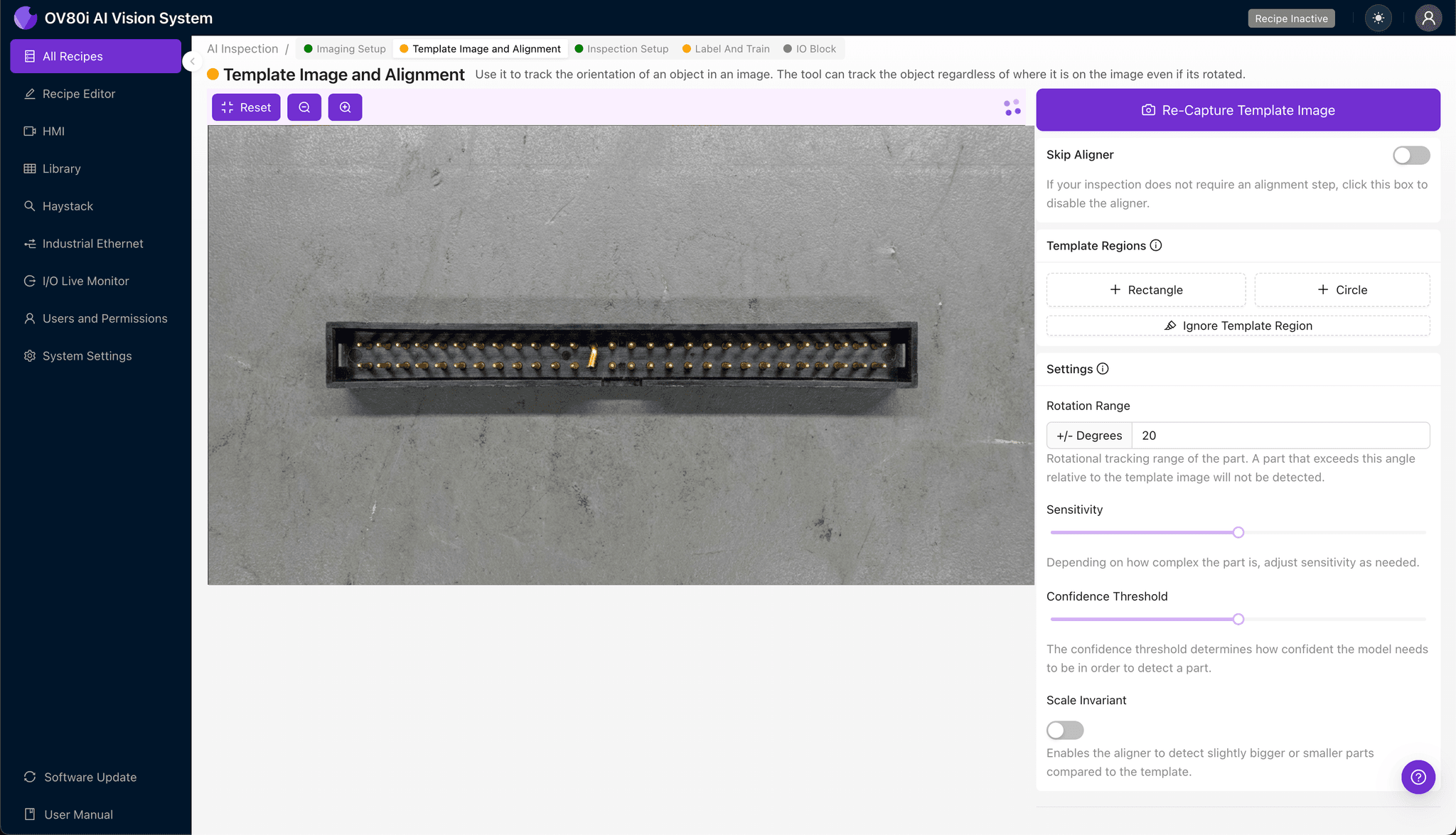
Step 2: Image Alignment
Navigate to "Template Image" in the configuration menu. Capture a template shot of a known-good header centered in the field of view.
Click "+ Rectangle" to add an alignment region around the header's main housing body. This gives the system a reliable reference feature for tracking position as headers move through the inspection station.
Set "Rotation Range" to 20 degrees to accommodate slight orientation variations as headers arrive on the conveyor.
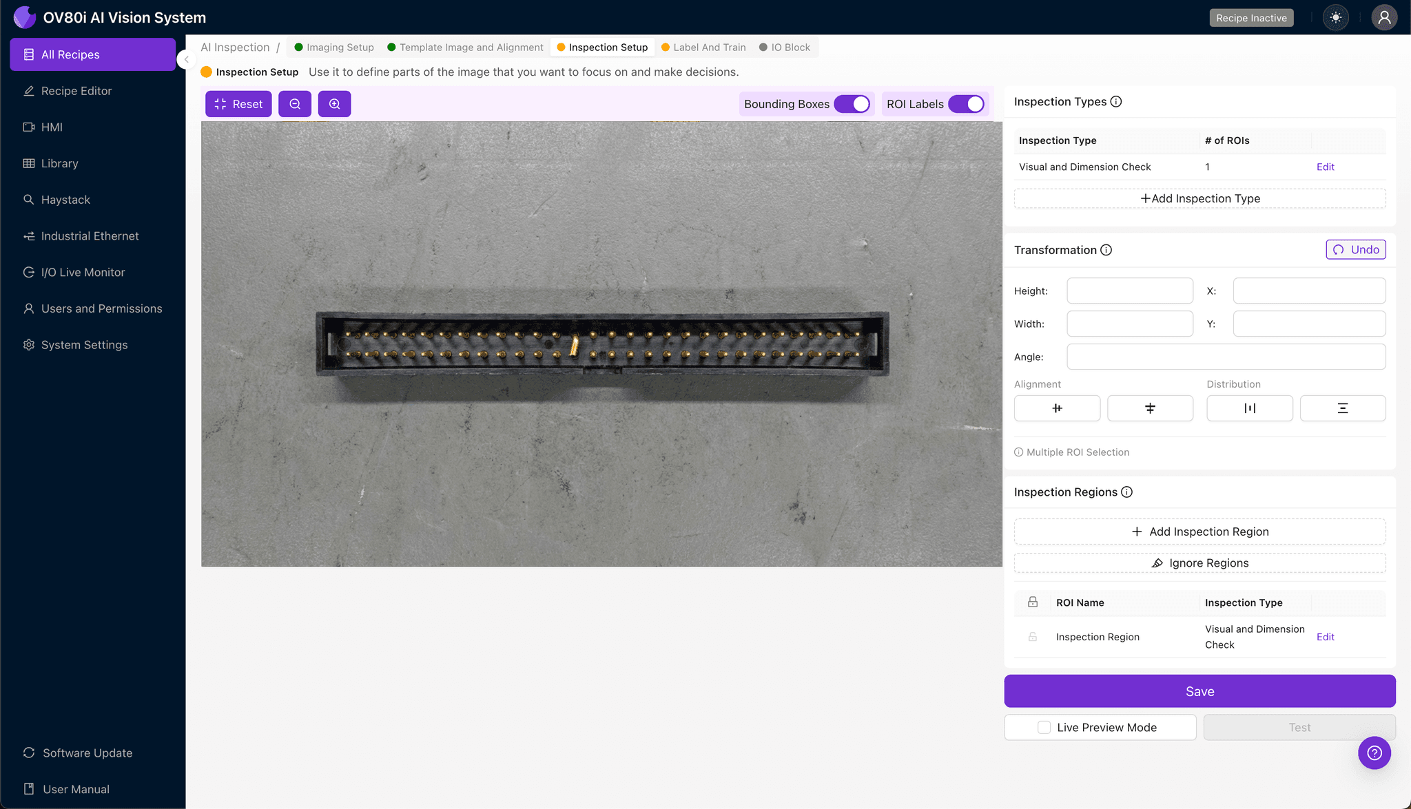
Step 3: Inspection Region Selection
Navigate to "Inspection Setup" to define your detection zones. Rename your "Inspection Types" to match your defect categories—for example, "Stub_Length," "Pin_Alignment," and "Housing_Integrity."
Click "+ Add Inspection Region" for each critical area. Resize the yellow bounding box to cover the stubbed pin array, focusing tightly on the trimmed pin tips where length defects occur.
Add additional regions for the housing perimeter and pin base areas. Click "Save" to confirm all inspection zones.

Step 4: Labeling Data
The human-in-the-loop labeling process trains your AI model to recognize your specific defect criteria. As production images flow in, operators review and categorize each capture.
Label images as Good or Bad based on your quality standards. Include representative samples of acceptable variation alongside clear examples of each failure mode—inconsistent stub lengths, burrs, bent pins, and plating issues.
Aim to capture edge cases—headers that barely pass and those that barely fail. This boundary data dramatically improves model accuracy for detecting subtle stub length variations.
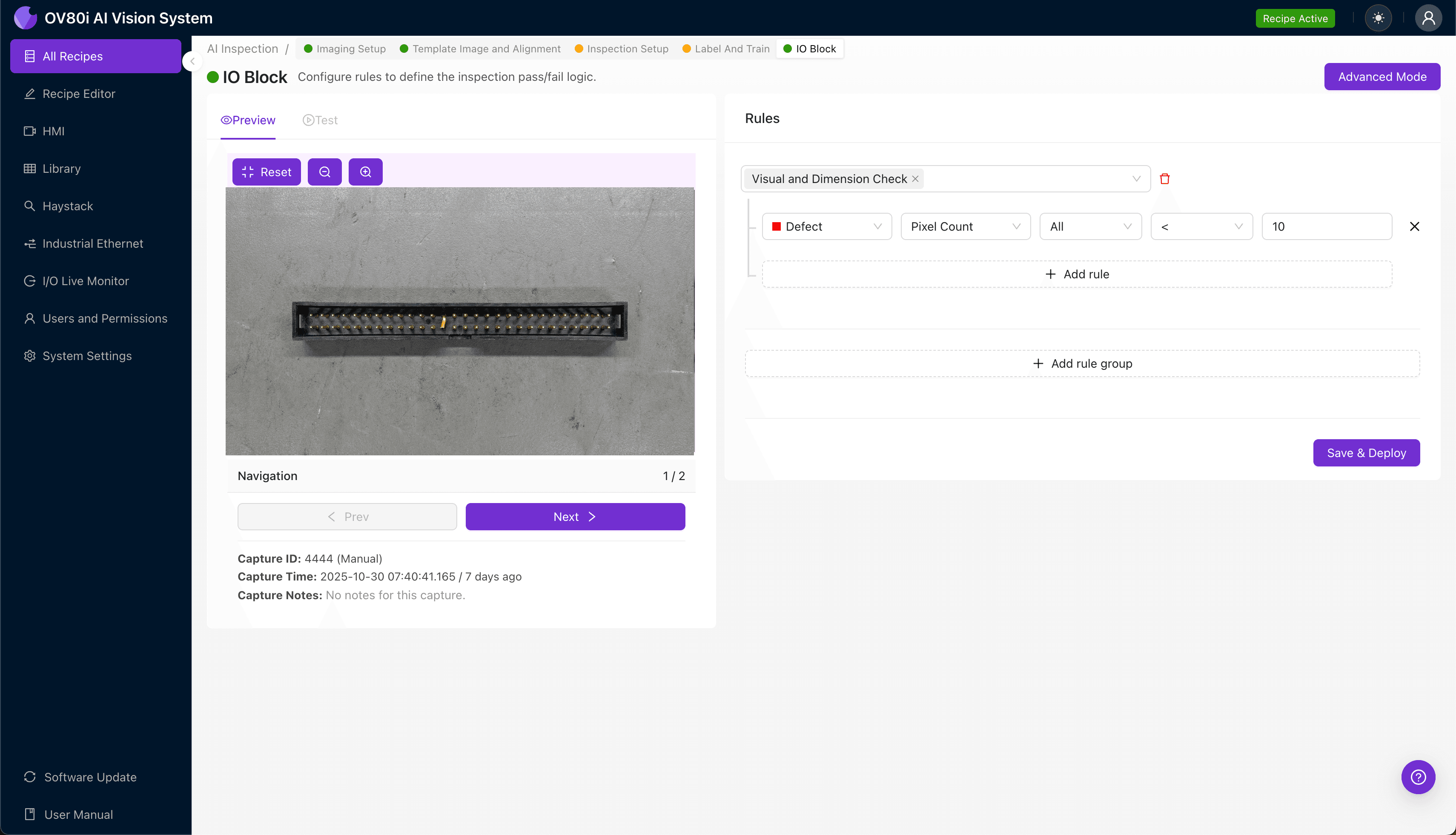
Step 5: Creating Rules
Navigate to the rules engine to set pass/fail logic based on your Inspection Types. Configure thresholds that match your quality specifications—for example, flagging any header where stub length confidence falls below 95%.
These rules gate automated acceptance on your production line. Headers that pass proceed to packaging; flagged units divert to secondary inspection or reject bins automatically.
Key Outcomes & ROI
Implementing AI-powered inspection for stubbed pin headers delivers measurable business impact:
- Reduced scrap rates — Catch defects before headers ship, eliminating costly customer returns and field failures in mission-critical systems
- Higher throughput — Inspect 100% of production at full line speed without adding headcount or creating inspection bottlenecks
- Enhanced compliance and traceability — Automatically log every inspection with timestamped images for audit trails required in aerospace and telecom applications
- Process improvement insights — Analyze defect trend data to identify upstream manufacturing issues with the stubbing process before they escalate
Eliminate Stubbed Pin Defects Today
Stop relying on fatigued inspectors for your high-speed connector QC. Deploy Overview.ai to catch stub length variations and pin defects automatically.