
Connector PinInspection
Bent pins, true position drift, plating pitting, and uneven seating depth. High-density connectors fail in dozens of subtle ways that pin gauges miss. We score every pin individually.
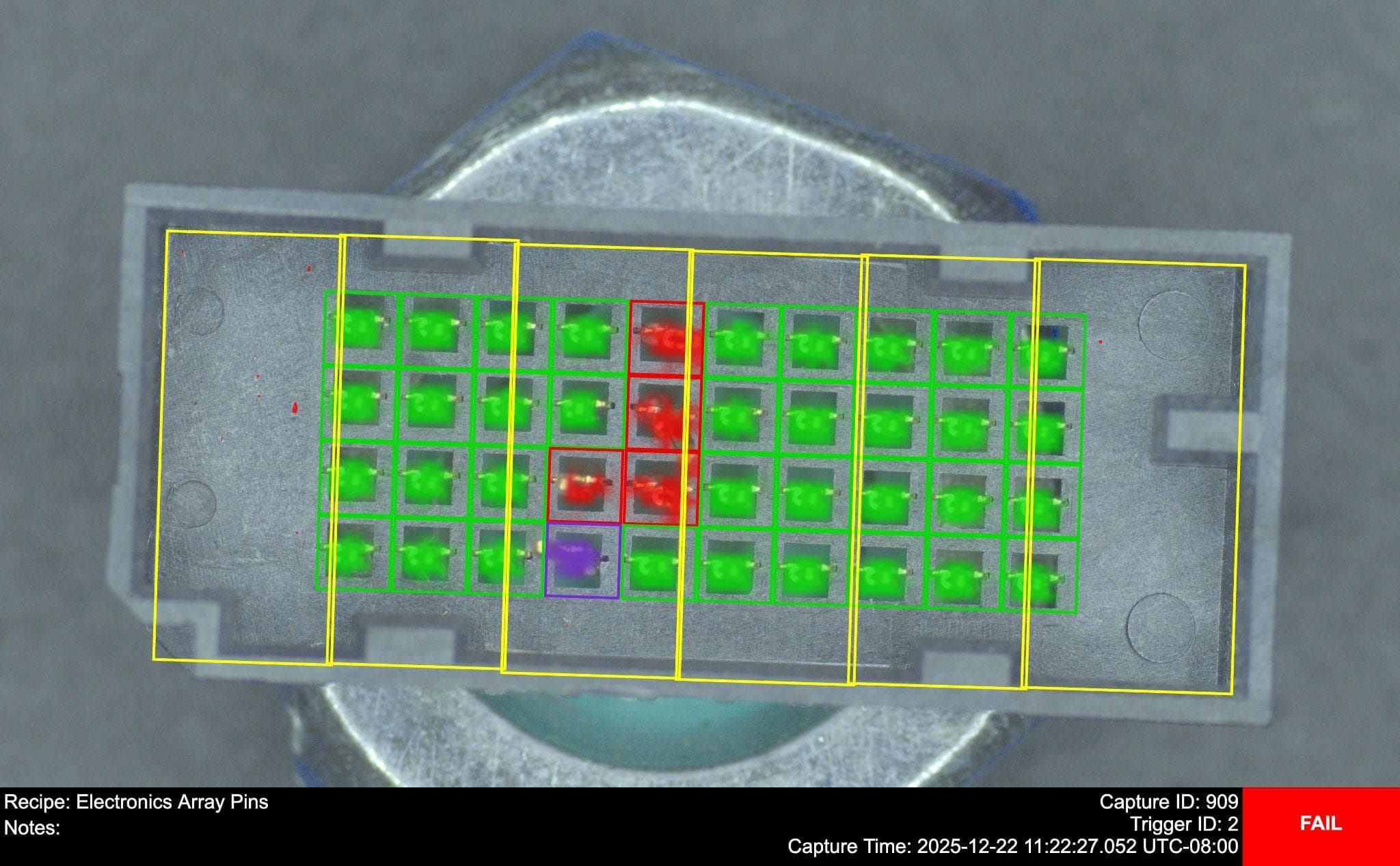
High-density connector pin array from a customer assembly
The Defects We Catch on Pins
Real defect imagery from connector manufacturing customers.
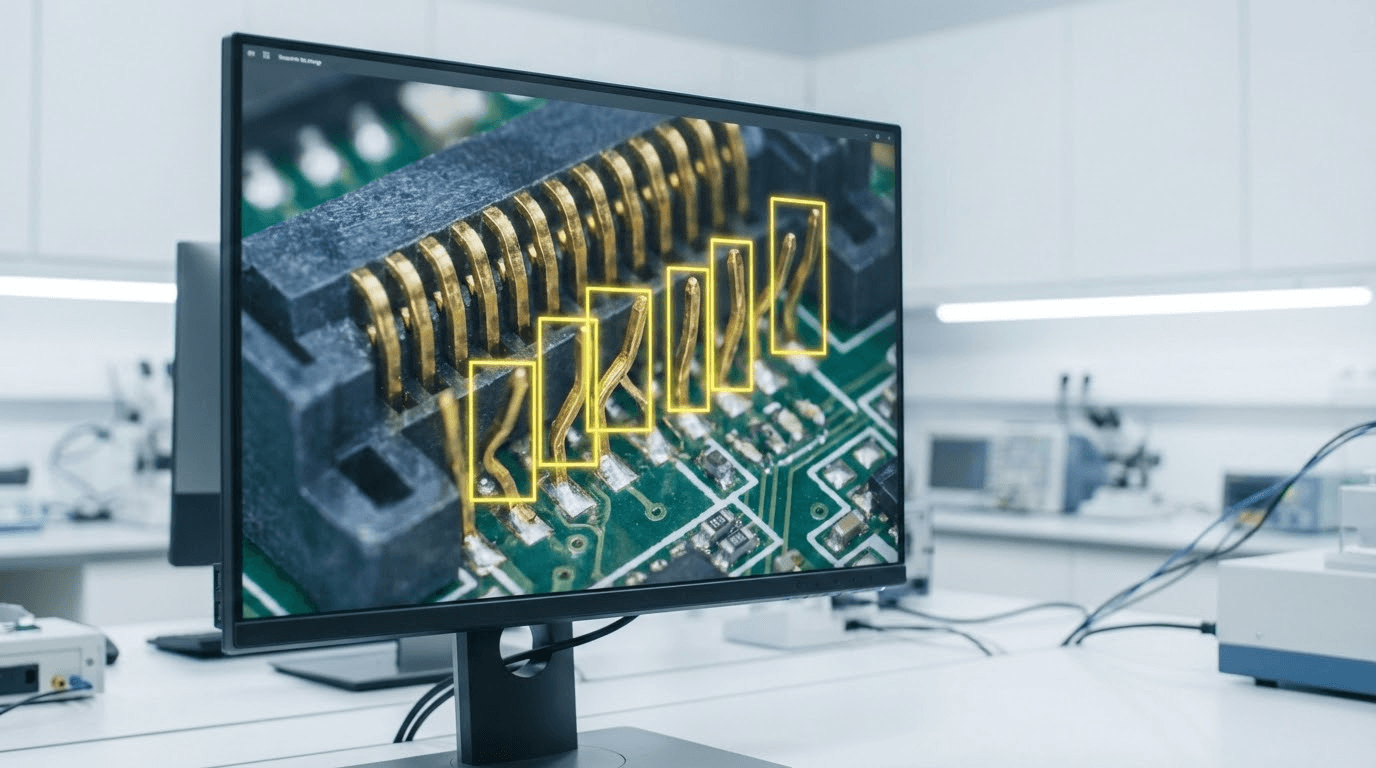
Bent and skewed signal contacts
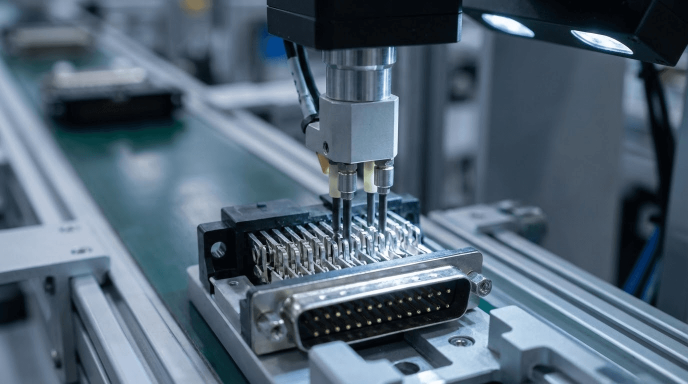
Uneven seating depth and retention
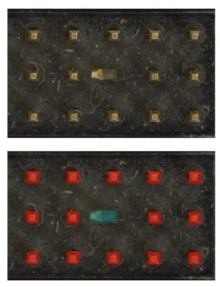
AI classifying every pin in a high-density array
Pin Defects We Catch
Bent & Buckled Pin Detection
Press-fit, compliant, and signal pin connectors all suffer mechanical handling damage that produces bent tips, lateral skew, and buckled shoulders. These faults pass contact pin gauges and silently produce intermittent field failures. Overview AI catches each pin individually across an OSFP host, QSFP-DD, or high-density backplane connector, with per-pin pass/fail and a fault map back to the operator HMI.
True Position & Seating Depth
Uneven seating depth on press-fit and compliant pins compromises retention force and signal continuity. Subtle true position drift in high-density arrays produces crosstalk barriers and impedance mismatch. The OV80i resolves the geometry at sub-pixel accuracy, scoring each pin against the nominal datum and flagging trend drift hours before scrap rates climb.
Plating & Surface Defects
Coax center pins and gold-plated contacts arrive from plating with defects that contact resistance testing cannot see: bath pitting, plating thinning, scratches, foreign material, and oxidation. Our system trains on real plating-line examples and flags each defect class with pixel-level localization, supplementing or replacing destructive cross-section sampling.
Unified High-Density Connector QC
A leading high-density connector manufacturer consolidated four separate inspection stations onto a single Overview AI platform: bent pin detection, BGA solder ball inspection, wafer alignment for crosstalk barriers, and final-assembly cosmetic check. The unified workflow reduced false rejects and gave their reliability engineers one source of truth for every connector defect class.
Built for High-Density Connectors
Density keeps climbing. Defect modes keep multiplying. The model keeps up.
Per-Pin Resolution
Score every pin individually. No averaging away a single bent contact across the array.
Reliability Audit Trail
Every connector logged with its inspection image, fault map, and timestamp. Built for IATF and AS9100 audits.
Add New Defect Classes Anytime
New connector geometry, new defect mode, new plating chemistry. Retrain in under an hour without vendor involvement.
FAQ
Frequently asked questions
Why are connector pins one of the harder vision tasks?
Three things stack up. The features are small, so resolution is tight. There are many of them, so one bad pin in a hundred has to be caught rather than averaged away. And the pins are bright plated metal, which reflects unpredictably and throws highlights that look like feature edges. On top of that, a bent pin may only deflect a fraction of a millimetre, so the field of view usually has to be tightened until that deflection covers several pixels, which often means more than one view per connector.
How is glare on plated pins controlled?
With diffuse light, and by deciding where the specular return goes. Bright metal reflects the light source, so a point source produces a hot spot that can read as an edge or hide a real defect underneath it. Diffuse illumination spreads the return so what the camera sees is the pin geometry rather than a reflection of the lamp. Photometric approaches, which capture the same pins under several lighting directions, go further and separate true surface shape from reflection, which is what makes a subtle deformation measurable.
We build hundreds of connector variants. Does each one need its own setup?
That is the real problem with connectors, more than any single inspection. The variants share a platform, so the inspection is conceptually the same across all of them, but a system that needs rebuilding per variant turns every new SKU into an engineering project. The practical answer is deploying one recipe across a family and generating the training data for new variants rather than collecting it, so coverage scales with the platform instead of with the part count.
Ready to Catch Every Bent Pin?
Send us a sample run. We will return a working pilot model in days, not months.