
Hot Bar SolderingInspection
Fine-pitch solder QC at production speed. Hot bar bonding leaves no margin for bridges, tombstoning, or insufficient wetting. We catch every joint, every cycle, with X-Y fault data routed straight to your PLC.
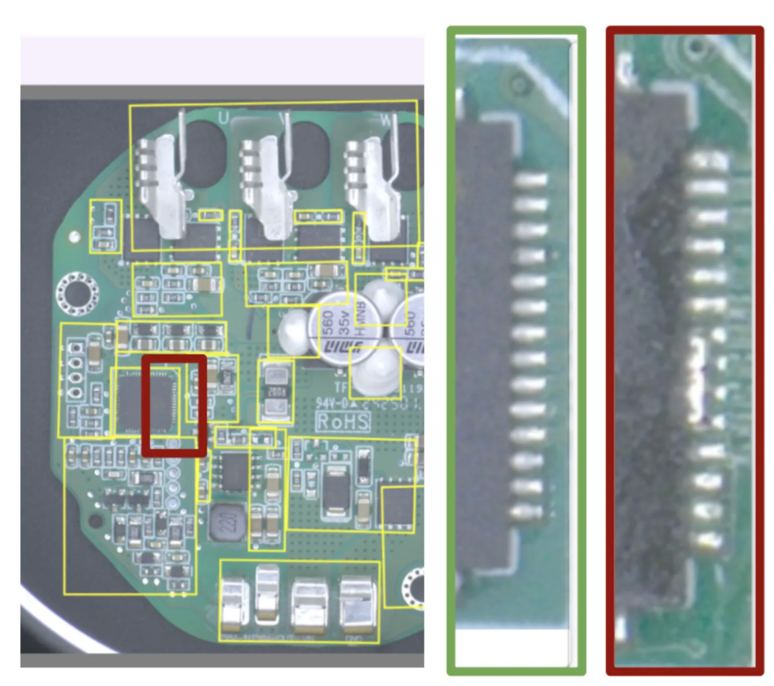
Solder bridge defect, the kind we catch at line speed
The Defects We Catch on Soldered Joints
Real defect imagery from electronics manufacturing customers.
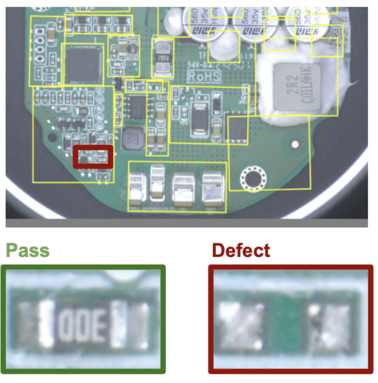
AI pass/defect on a populated PCBA
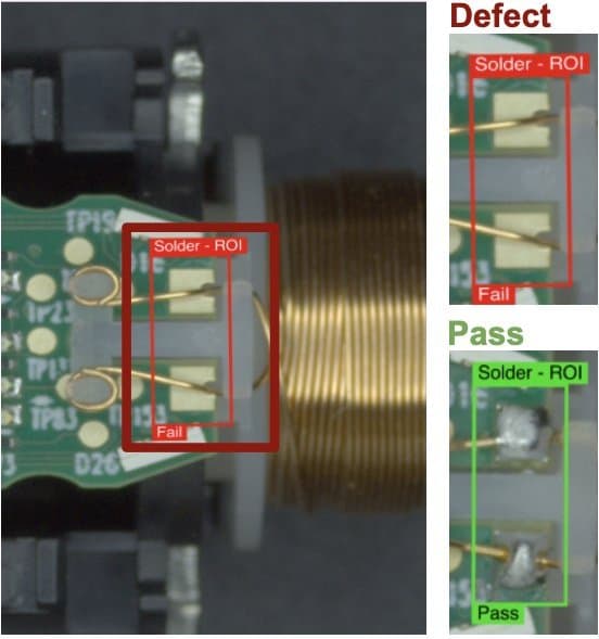
Real Pass and Defect calls on solder joints
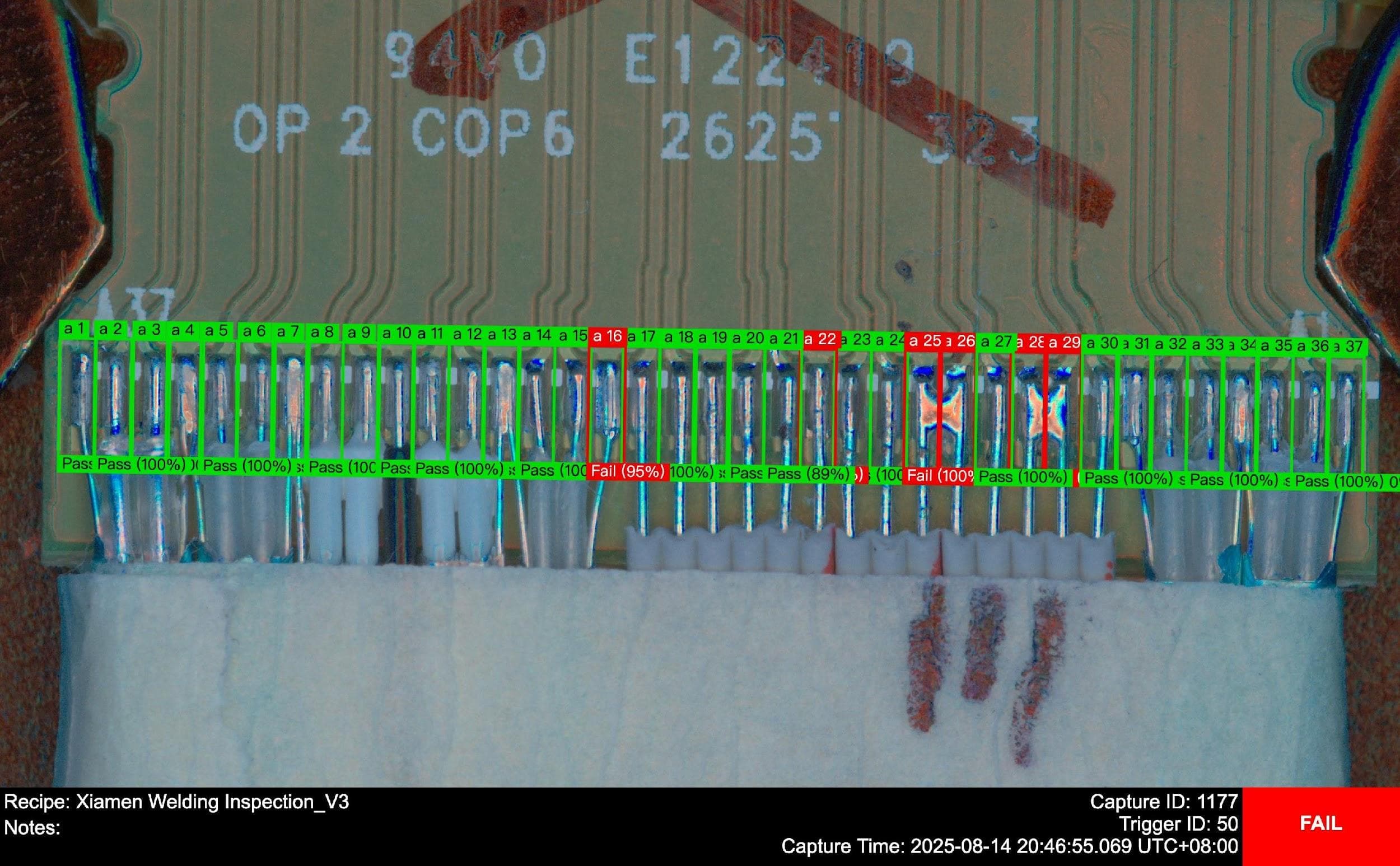
Per-pin Pass and Fail calls on soldered leads
Solder Defects We Catch
FPC and Flex Circuit Bonding
Hot bar bonding to flexible printed circuits operates on sub-0.5 mm pad pitches where any solder bridge or skip fails the assembly. Traditional AOI struggles with the reflective polyimide substrate and shallow joint geometry. Overview AI trains on a small set of real production samples and reliably classifies solder bridge, insufficient solder, cold joint, lifted pad, and substrate scorch.
Laser and Hot Bar Reflow on Connectors
Pluggable connectors and DAC paddle cards rely on hot bar reflow to terminate dozens of contacts at once. Tin balls, solder bridging, tin tips, low overlap, insufficient solder, solder deviation, and false welding all compromise signal integrity. Our system trains with a small set of examples and detects all common issues even under glare or variable joint geometries.
BGA & Fine-Pitch Solder Ball Inspection
Ball voiding, missing balls, and ball splash on BGA and automotive Ethernet header reflow create field failures that traditional rule-based vision cannot reliably segment. Overview AI handles the reflective specular variation across the ball surface and provides per-ball pass/fail with pixel-level localization. Faults map directly to X-Y coordinates the operator can act on.
Auto Line Pause and PLC Integration
A major electronic chip manufacturer eliminated escapes from minor soldering defects by integrating Overview AI directly with the PLC. Node-Red logic on the camera pauses the line on any failure and pushes X-Y fault coordinates to the operator HMI. No PC. No middleware. No additional license servers.
Why Electronics Manufacturers Choose Us
Train, deploy, and retrain on the same hardware that runs your production inspection.
Handles Reflective Joints
AI models adapt to specular glare, oxidation variability, and flux residue that breaks rule-based vision and AOI.
X-Y Fault Mapping
Defects flow to the HMI with exact coordinates, so the operator does not have to hunt for the failed joint.
No Special Vision Team
Your process engineers train models from a browser. No PhDs, no system integrators, no waiting on the OEM.
FAQ
Frequently asked questions
What does a good hot bar joint look like to a camera?
Three things together: a consistent fillet along the joint, evidence that the solder wetted the pad rather than sitting on it, and no bridge to the neighbouring pad. The failure modes are subtler than a missing joint. Too little heat leaves a cold joint that looks nearly right but has poor wetting and will fail later. Too much leaves discoloration around the bond and can damage the substrate. Because the difference between good and marginal is appearance rather than a dimension, showing a model accepted and rejected joints works better than trying to write a rule for fillet geometry.
Can it catch a cold joint, or does that need electrical test?
Vision catches a useful share of them, and it catches them earlier. A cold joint usually has a visible signature in the wetting: the solder beads rather than flowing, the fillet angle is wrong, the surface is duller. That is detectable and it is detectable at the station that caused it, which is the point. It is not a replacement for electrical test, because a joint can look right and still be marginal. Treating vision as the fast in-line filter and electrical test as the confirmation is the sensible split.
The joints are small and shiny. What does the optics need to do?
Get enough pixels on the fillet and control the specular return. Solder is bright and curved, so it throws highlights that can read as an edge or hide a real feature. Diffuse illumination flattens those highlights so the fillet shape is what the camera sees, and a tight field of view puts enough pixels across a joint that is often only a millimetre or two wide. Multiple pads in one frame is fine, as long as the resolution per pad still holds.
Ready to Eliminate Solder Escapes?
See how a pilot model trained on your samples performs in your line conditions.