
Detecting Scuffed Thermal Interface Material on 800G Optical Modules
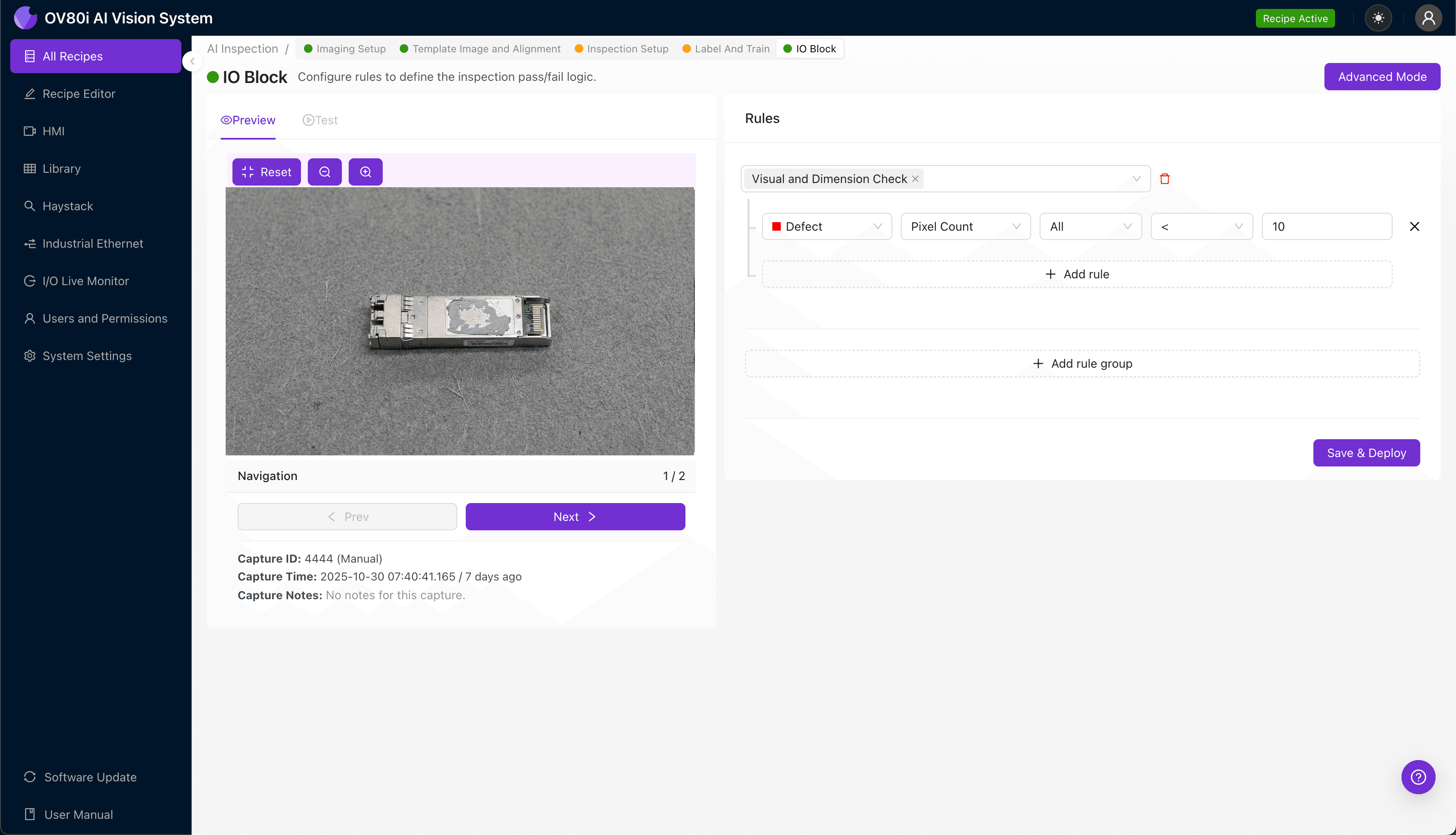
"Scuffed thermal interface material on 800G optical modules creates hidden thermal resistance that leads to premature failures. Overview.ai's machine vision system detects these subtle surface defects at full production speed, ensuring every module meets thermal performance requirements before final assembly."
The Problem: Why TIM Defects Threaten 800G Module Reliability
As data center bandwidth demands surge toward 800G and beyond, optical transceiver modules face unprecedented thermal management challenges. The thermal interface material (TIM) between high-power DSP chips and heat sinks is critical—any surface damage compromises heat transfer and risks premature module failure.
Common TIM Defects in 800G Module Production:
- Surface scuffing and abrasions — scratches from handling tools or automated pick-and-place operations
- Uneven TIM application thickness — inconsistent paste spread causing thermal hotspots
- Air voids and bubbles — trapped air pockets that create thermal resistance
- Contamination and foreign particles — dust, fibers, or debris embedded in the TIM surface
- Delamination at edges — separation between TIM and substrate surfaces
- Insufficient coverage zones — areas where TIM fails to contact the die or heat spreader
Manual inspection of TIM quality is notoriously unreliable at production speeds. Human inspectors experience fatigue-induced inconsistency, especially when examining dozens of modules per hour under magnification. The subtle surface variations that indicate scuffing are often invisible under standard lighting conditions, making defects easy to miss.
The Solution: AI-Powered Visual Inspection
Machine vision systems equipped with deep learning overcome the limitations of human inspection by maintaining consistent, objective evaluation across every single unit. Unlike rule-based systems that struggle with the variable appearance of TIM defects, neural networks learn to recognize the full spectrum of scuffing patterns—from light surface marks to severe abrasions.
Overview.ai's approach enables 100% inline inspection at production speeds without sacrificing accuracy. The OV80i system captures high-resolution images and applies trained AI models in milliseconds, flagging defective modules before they proceed downstream.
Step 1: Imaging Setup
Position the 800G optical module under the OV80i camera with the TIM surface facing upward. Ensure consistent placement using a fixture or nest that matches your production line handling.
Click "Configure Imaging" in the Overview interface. Adjust Camera Settings including exposure time and gain to highlight surface texture variations—scuffed TIM often appears differently under controlled lighting angles.
Click "Save" to lock in your imaging configuration.
Step 2: Image Alignment
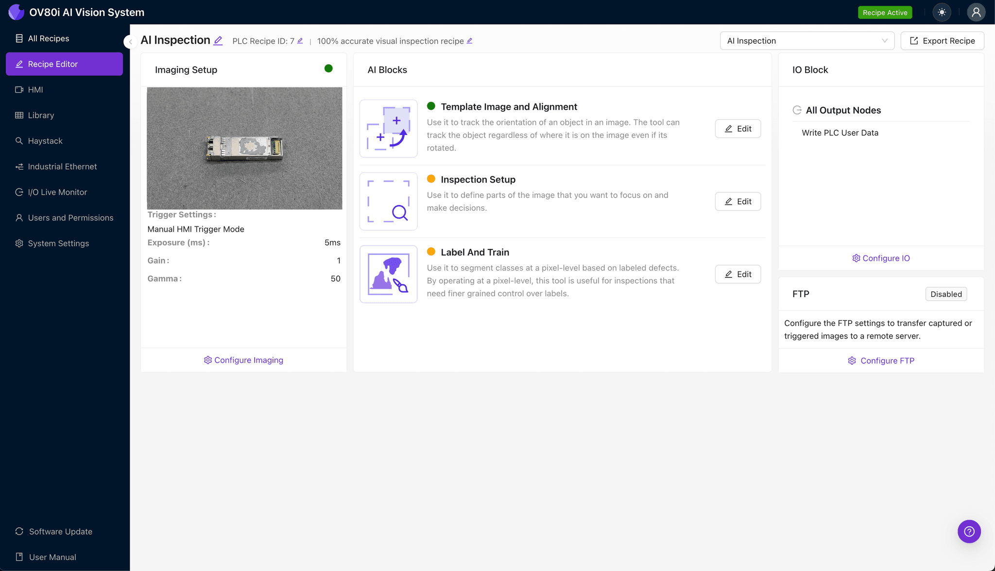
Navigate to the "Template Image" section and capture a reference image of a correctly positioned module. This template enables the system to automatically align incoming units regardless of minor placement variations.
Click "+ Rectangle" to add an alignment region around the main module body or distinctive features like the housing edge. Set the "Rotation Range" to 20 degrees to accommodate expected orientation variability on your line.
Step 3: Inspection Region Selection
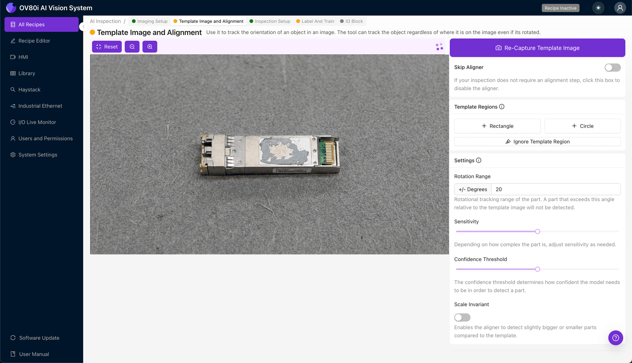
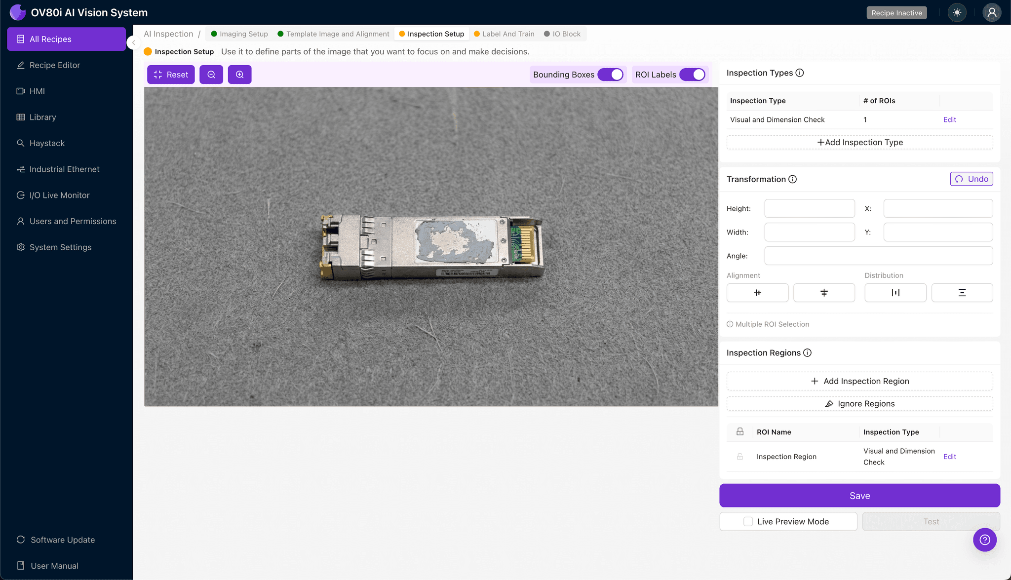
Navigate to "Inspection Setup" to define where the AI should focus its analysis. Rename your "Inspection Types" to descriptive labels such as "TIM_Surface_Quality" or "Thermal_Pad_Integrity."
Click "+ Add Inspection Region" to create a new zone. Resize the yellow bounding box to cover the thermal interface material surface area—include the full TIM footprint plus a small margin.
Click "Save" to confirm your inspection regions.
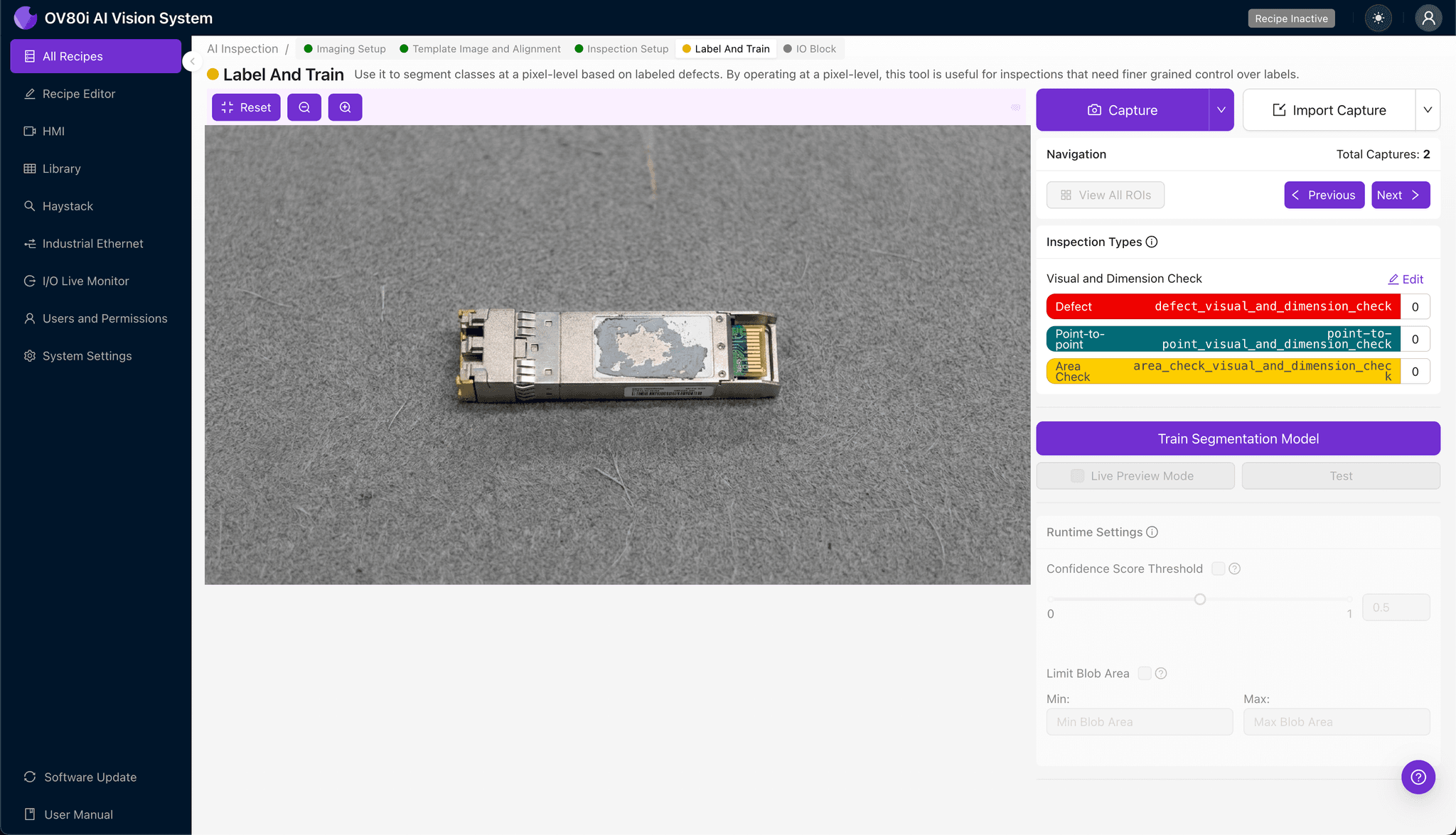
Step 4: Labeling Data
This human-in-the-loop phase trains the AI to distinguish acceptable TIM surfaces from defective ones. Review captured production images and label each as Good or Bad based on your quality standards.
Include representative samples across the full defect spectrum: light scuffs, deep scratches, and contamination. Incorporate known failure modes from customer returns or reliability testing to ensure the model catches field-relevant defects.
Step 5: Creating Rules
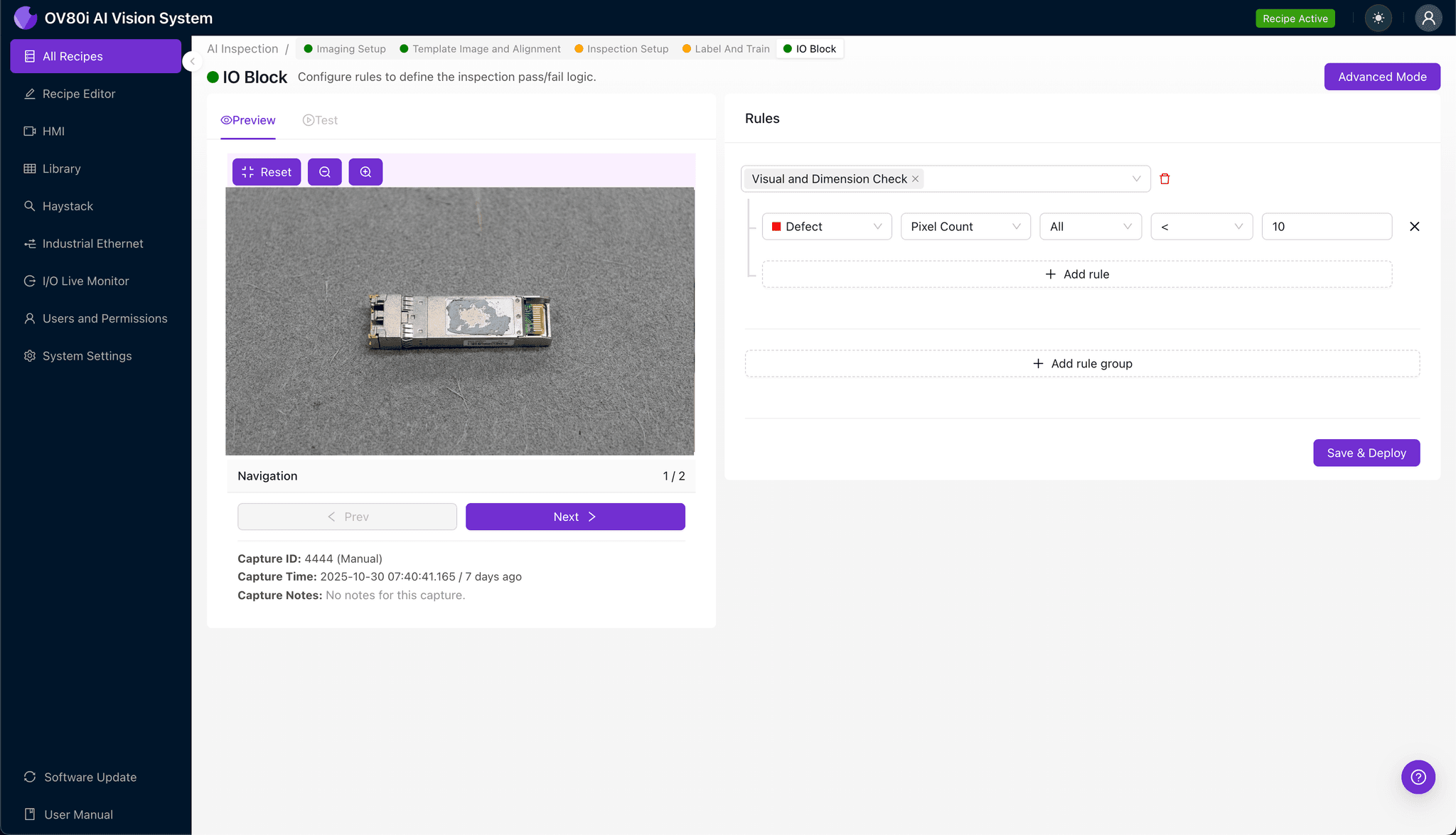
Define your pass/fail logic by setting thresholds for each Inspection Type. Configure the system to reject modules where TIM scuffing confidence exceeds your quality threshold.
Gate automated line acceptance on these rules—defective units are automatically diverted for rework or disposition, while passing modules continue downstream without operator intervention.
Key Outcomes & ROI
Implementing AI-powered TIM inspection delivers measurable business impact:
- Reduced scrap and rework costs — catch defects before modules undergo expensive final assembly and testing
- Higher throughput — eliminate inspection bottlenecks while achieving 100% coverage
- Compliance and traceability — maintain complete inspection records for customer audits and warranty analysis
- Process improvement insights — identify upstream handling issues causing TIM damage through defect trend analysis
Conclusion
Scuffed thermal interface material represents a silent reliability killer in 800G optical module production. With Overview.ai's visual inspection platform, manufacturers can detect these subtle defects consistently, objectively, and at full line speed—protecting both product quality and customer trust.
Eliminate TIM Defects Today
Stop relying on manual inspection for your 800G optical modules. Deploy Overview.ai to catch thermal interface material defects instantly.