
How to Detect Defects in Alignment Pins with Rough Surface Finish Using AI-Powered Visual Inspection
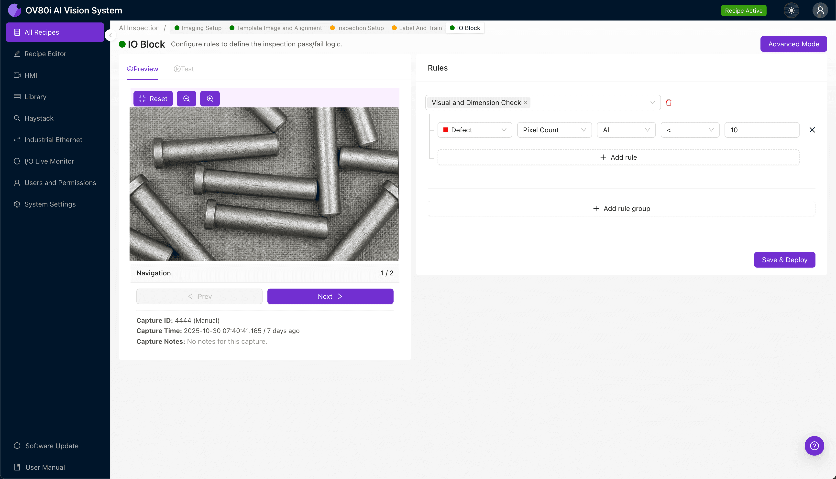
"Alignment pins with rough surface finish defects cause assembly failures and premature wear. Overview.ai's deep learning inspection catches tool marks, chatter, porosity, and scoring at full production speed—eliminating the inconsistency of manual inspection."
The Problem: Why Rough Surface Finish Defects Slip Through Traditional QC
Alignment pins are critical precision components that ensure accurate positioning in assemblies, fixtures, and tooling systems. When surface finish quality degrades, the consequences ripple through your entire production line—causing assembly failures, premature wear, and costly rework.
Common Defects Found in Alignment Pins with Rough Surface Finish:
- Excessive tool marks — Visible machining lines that exceed Ra specifications
- Surface porosity — Microscopic voids or pitting from material inconsistencies
- Chatter marks — Repetitive patterns caused by vibration during turning or grinding
- Burrs and raised edges — Material displacement along pin edges or chamfers
- Scoring and scratches — Linear surface damage from handling or secondary operations
- Inconsistent finish zones — Variations in roughness across different pin sections
Human inspectors struggle to maintain consistent judgment when evaluating surface texture at production speeds. Fatigue sets in quickly when examining hundreds of pins per hour, and subtle roughness variations become impossible to detect reliably under time pressure.
The Solution: Machine Vision + Deep Learning for Surface Finish Inspection
Traditional machine vision systems rely on rigid, rule-based programming that fails when surface defects vary in appearance. Deep learning changes this entirely—training AI models to recognize the subtle visual patterns that distinguish acceptable finish from rejectable roughness, just as an expert inspector would.
Overview.ai's approach delivers consistent, objective inspection at full line speed. The OV80i system captures high-resolution imagery of every alignment pin, analyzes surface characteristics in milliseconds, and flags defects that human eyes miss—without fatigue, without bias, and without slowing production.
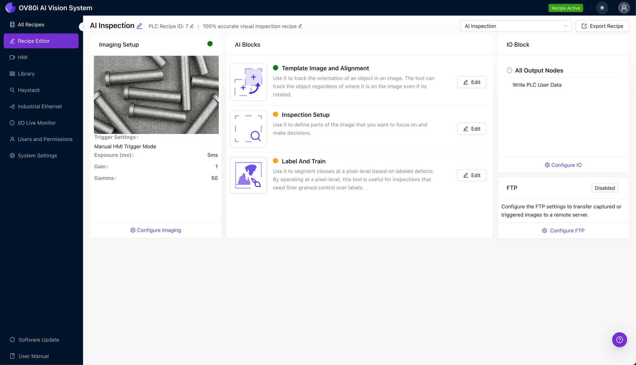
Step 1: Imaging Setup
Position your alignment pin under the OV80i camera, ensuring the lighting angle highlights surface texture variations. Angled or diffuse lighting often works best for revealing roughness defects that would appear flat under direct illumination.
Click "Configure Imaging" to access the Camera Settings panel. Adjust exposure and gain until surface details—including subtle tool marks and texture variations—are clearly visible without overexposure on reflective areas.
Click "Save" to lock in your optimized imaging parameters.
Step 2: Image Alignment
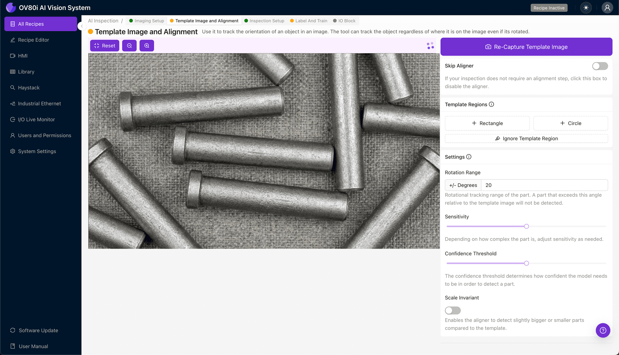
Navigate to the "Template Image" section in the software interface. Capture a Template image of a correctly positioned alignment pin to serve as your reference standard.
Click "+ Rectangle" to add a region around the main body of the pin. Set the "Rotation Range" to 20 degrees to accommodate minor orientation variations as pins enter the inspection zone.
Step 3: Inspection Region Selection
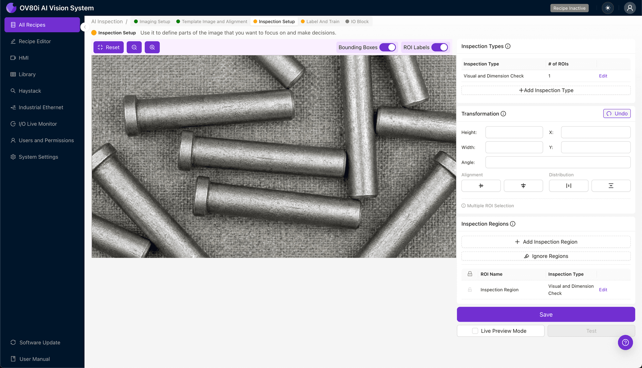
Navigate to "Inspection Setup" to define where the system should look for defects. Rename your "Inspection Types" to match your quality criteria—for example, "Surface_Roughness_Body" and "Chamfer_Finish."
Click "+ Add Inspection Region" to create targeted zones. Resize the yellow box to cover critical defect areas: the main cylindrical surface, chamfered edges, and any precision-ground sections.
Click "Save" to confirm your inspection regions.
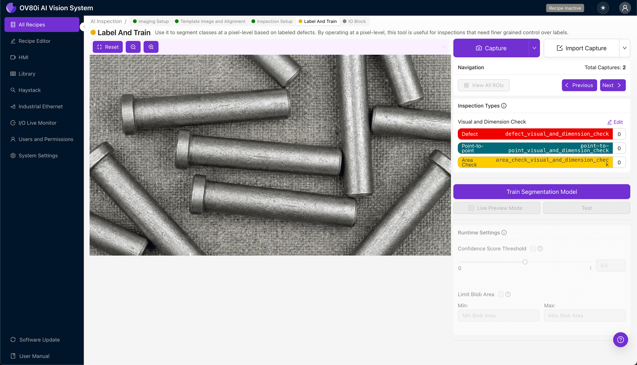
Step 4: Labeling Data
This human-in-the-loop process is where your quality expertise trains the AI. Review captured images and label each alignment pin as Good or Bad based on your surface finish specifications.
Include representative samples across your full range of acceptable variation. Deliberately add known failure modes—pins with excessive roughness, chatter marks, and scoring—to teach the model exactly what to reject.
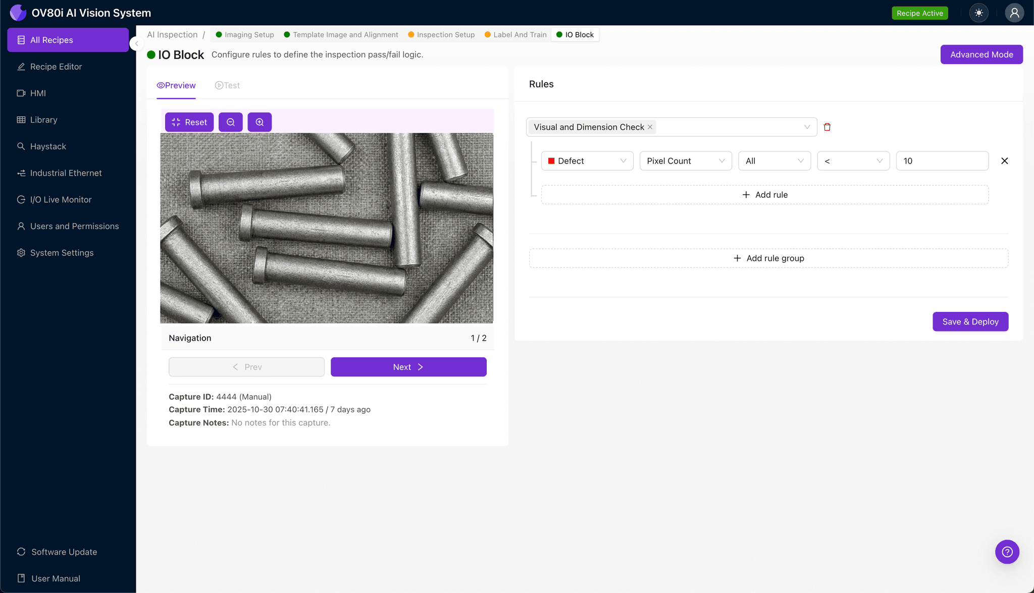
Step 5: Creating Rules
Define your pass/fail logic based on the Inspection Types you created. Set thresholds that match your quality standards—for example, flagging any pin where Surface_Roughness_Body confidence exceeds your defect threshold.
Gate automated acceptance on the line so that only pins meeting all criteria proceed to packaging or assembly. Rejected parts route automatically to quarantine for secondary review.
Key Outcomes & ROI
Implementing AI-powered inspection for alignment pin surface finish delivers measurable business impact:
- Reduced scrap rates — Catch defects before they reach downstream processes or customers
- Higher throughput — Inspect 100% of production without creating bottlenecks
- Enhanced compliance and traceability — Maintain complete inspection records with timestamped images for every part
- Process improvement insights — Identify upstream issues (tooling wear, material batch problems) through defect trend analysis
Ready to Eliminate Surface Finish Escapes?
Overview.ai's visual inspection platform transforms how manufacturers approach alignment pin quality control. Stop relying on inconsistent manual checks and start catching every defect—at production speed.