
How to Detect Bent Connector Tails (Non-Coplanar) with AI-Powered Visual Inspection
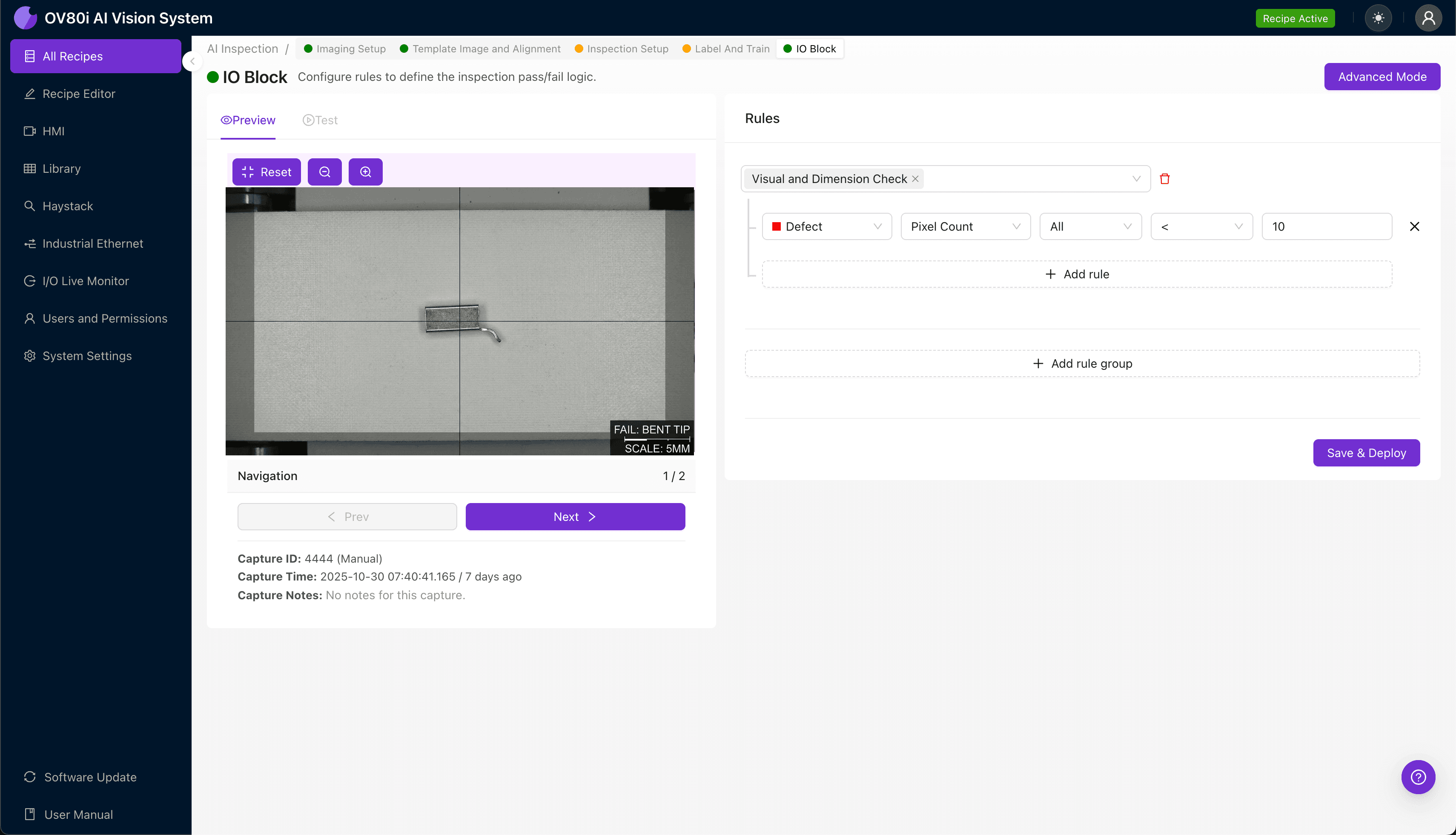
"Bent connector tails with coplanarity deviations as small as 0.1mm are virtually impossible to detect consistently through manual inspection. AI-powered machine vision eliminates human variability, catching every non-coplanar defect at full production speed without fatigue or bias."
The Problem: Why Bent Connector Tails Slip Through Manual Inspection
Connector tails—the protruding pins or leads that enable electrical connections—must maintain precise coplanarity to ensure proper mating and reliable signal transmission. When even a single tail bends out of plane, the entire connector assembly can fail during downstream processes or in the field.
Manual inspection of these defects is notoriously unreliable. Human inspectors experience fatigue after just 20-30 minutes of repetitive visual tasks, and coplanarity deviations of 0.1mm or less are virtually impossible to detect consistently with the naked eye at production speeds.
Common Defects Found in Connector Tails with Bent Tips (Non-Coplanar):
- Lateral tip deflection — Pin tip bent sideways, deviating from the vertical axis
- Forward/backward lean — Tail tilted along the insertion plane, affecting seating depth
- Twisted or rotated pins — Individual tails rotated on their axis, causing misalignment
- Uneven pin height (Z-axis deviation) — Tips not terminating at the same plane level
- Splayed pin clusters — Multiple adjacent tails fanning outward from center
- Compound bends — Tails exhibiting multiple deflection points along their length
The Solution: Machine Vision + Deep Learning
AI-powered visual inspection eliminates the variability inherent in human judgment. By training deep learning models on thousands of labeled images, the system learns to recognize subtle geometric deviations that indicate non-coplanar conditions—even when those deviations occur at angles or under lighting conditions that would fool a human eye.
Overview.ai's approach delivers consistent, objective inspection at full line speed. The OV80i system captures high-resolution images of every connector, analyzes them in milliseconds, and makes pass/fail decisions without slowing production or introducing inspector bias.
Step 1: Imaging Setup
Position the connector tail assembly under the OV80i camera, ensuring the pin tips are clearly visible in the field of view. Angled lighting or backlighting often works best to accentuate tip deflection and create contrast against the connector body.
Click "Configure Imaging" in the Overview.ai interface. Adjust Camera Settings—including exposure time and gain—until bent tips cast distinct shadows or reflections that differentiate them from straight pins.
Click "Save" to lock in your imaging parameters.
Step 2: Image Alignment
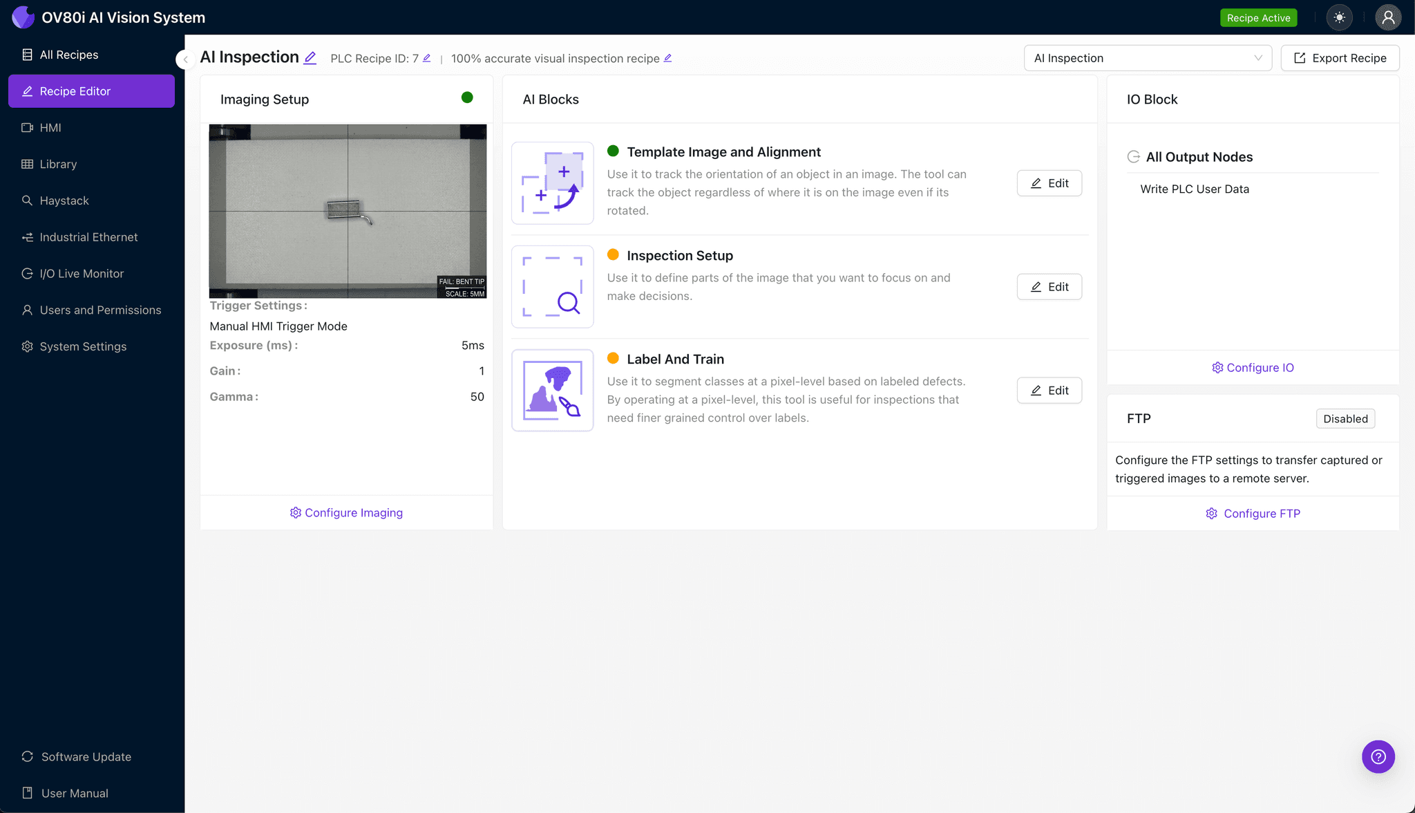
Navigate to the "Template Image" tab and capture a reference image of a known-good connector. This template ensures the system can locate and orient each part consistently, even if connectors arrive at slightly different positions on the line.
Click "+ Rectangle" to add an alignment region around the main connector body (excluding the tails themselves). Set the Rotation Range to 20 degrees to accommodate minor part rotation during handling.
Step 3: Inspection Region Selection
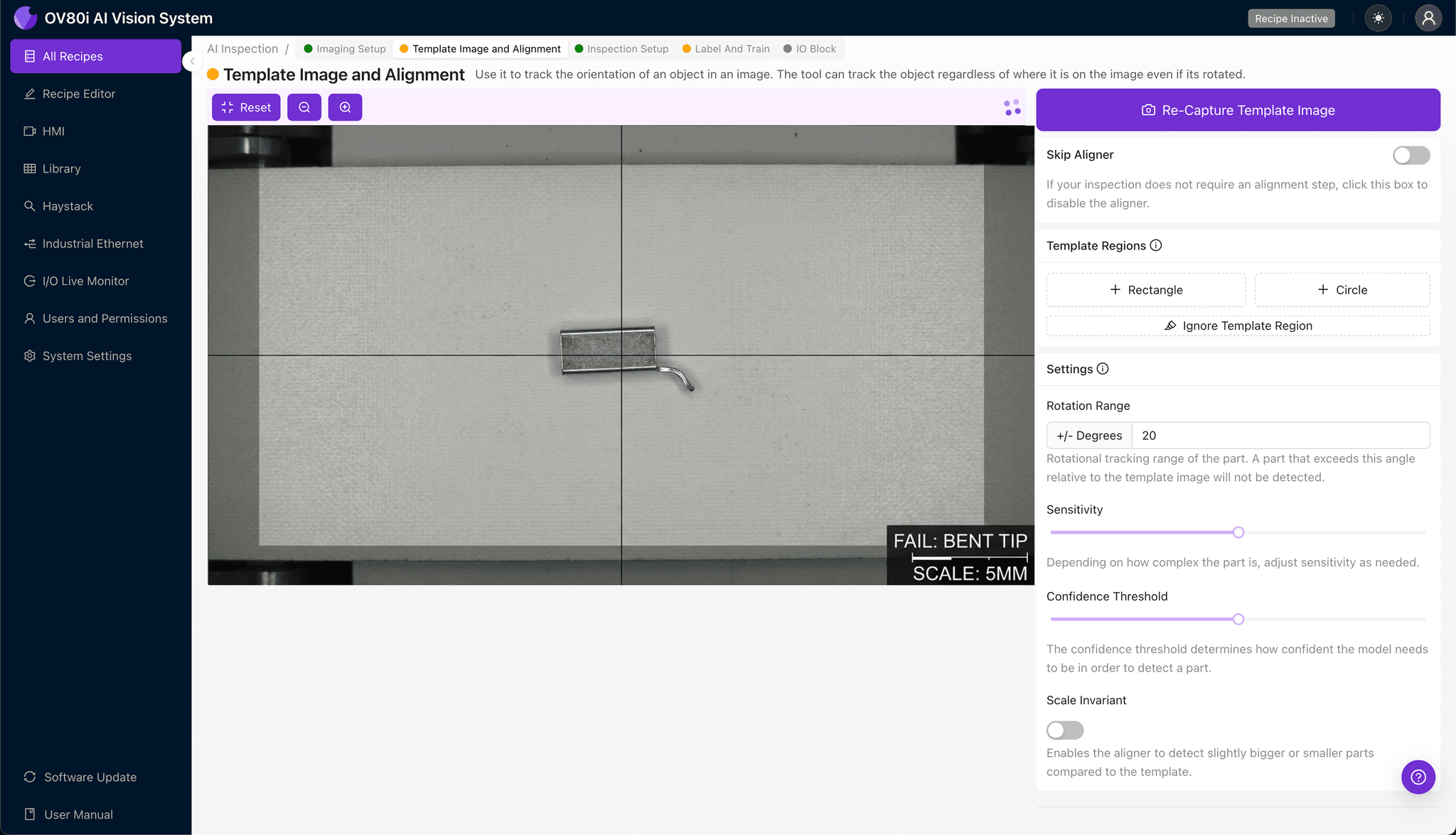
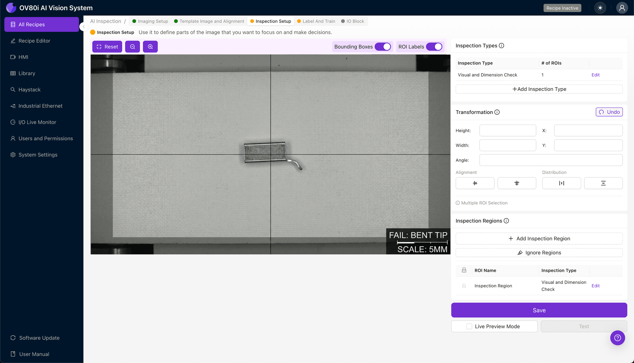
Navigate to "Inspection Setup" in the left-hand menu. Rename your Inspection Types to reflect the specific defect categories—for example, "Bent_Tip_Lateral" or "Non_Coplanar_Z."
Click "+ Add Inspection Region" to create a new zone. Resize the yellow bounding box to cover the critical defect area—typically the upper third of the connector tails where tip deflection is most visible.
Click "Save" to confirm your inspection regions.
Step 4: Labeling Data
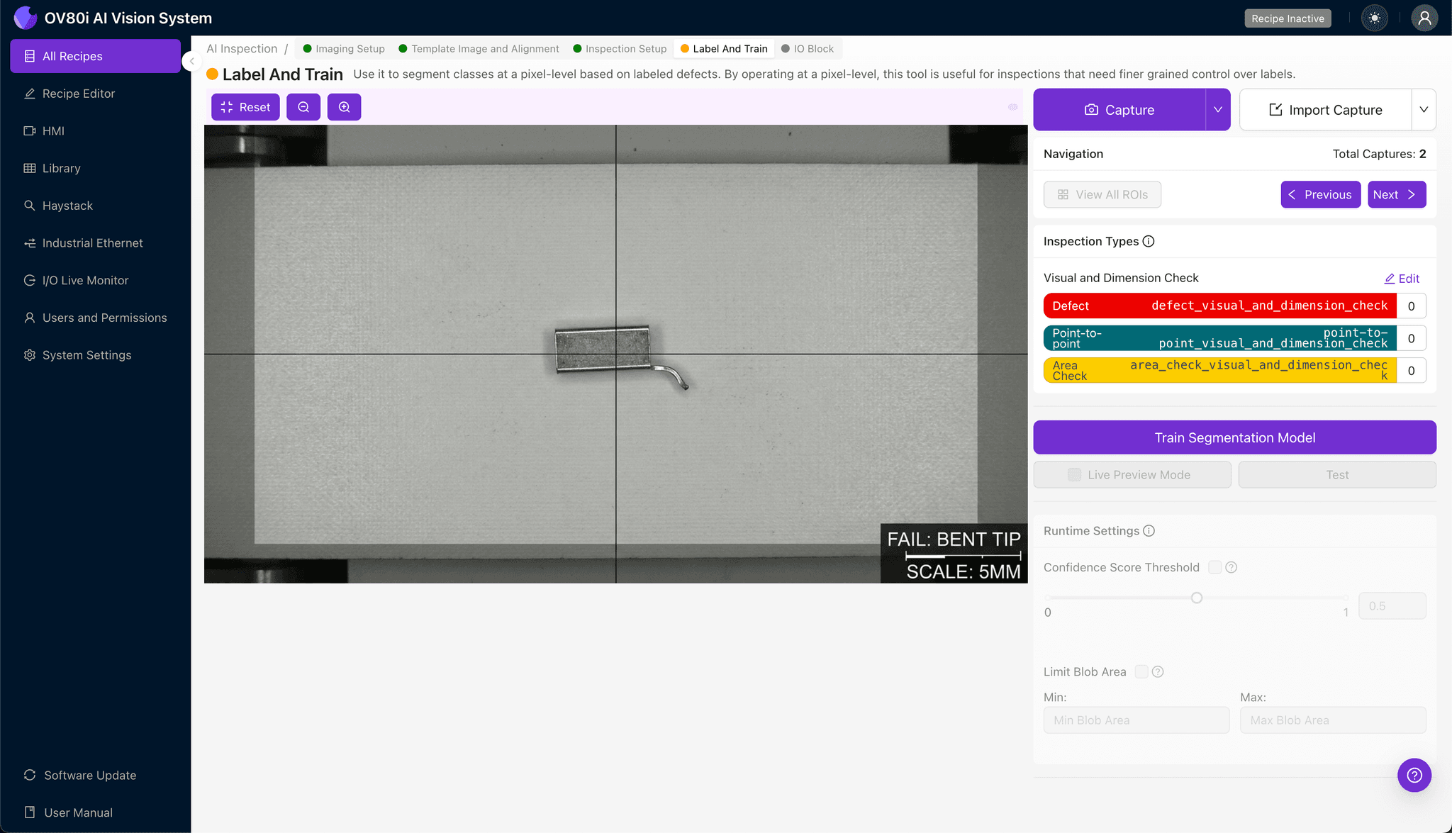
This is where human expertise trains the AI. Review incoming images and label each connector as Good (all pins coplanar within tolerance) or Bad (one or more bent tips detected).
Include representative samples across the full range of defect severity. Don't forget to add known failure modes from your historical reject data—this teaches the model to catch the specific bent-tip patterns your production line actually produces.
Step 5: Creating Rules
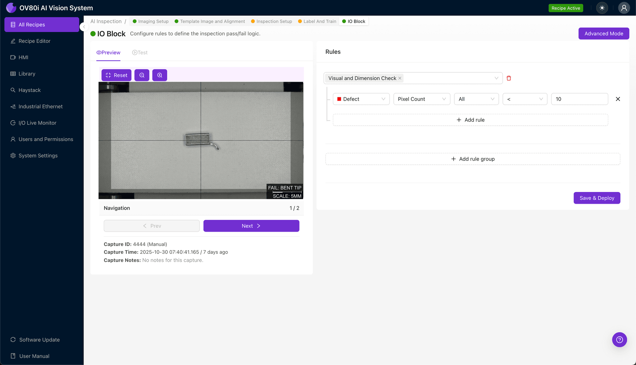
Define your pass/fail logic based on the Inspection Types you configured. For example, you might set a rule that flags any connector with a "Bent_Tip_Lateral" confidence score above 85% as a reject.
These rules gate automated acceptance on the line. Connectors that pass proceed to packaging; those that fail are diverted for rework or scrap—all without human intervention.
Key Outcomes & ROI
Implementing AI-powered inspection for bent connector tails delivers measurable business impact:
- Reduced scrap rates — Catch defects earlier in the process before additional value is added
- Higher throughput — Inspect 100% of parts at line speed without bottlenecking production
- Compliance and traceability — Automatically log images and inspection results for every unit, supporting ISO and customer audit requirements
- Process improvement insights — Identify upstream root causes by analyzing defect trends over time (e.g., tooling wear, feeder misalignment)
Ready to Eliminate Bent Connector Escapes?
Stop relying on fatigued inspectors and outdated sampling methods. Deploy Overview.ai to catch every bent tip, every time.