
How to Detect Connector Gasket Torn Conductive Layer Defects with AI-Powered Visual Inspection
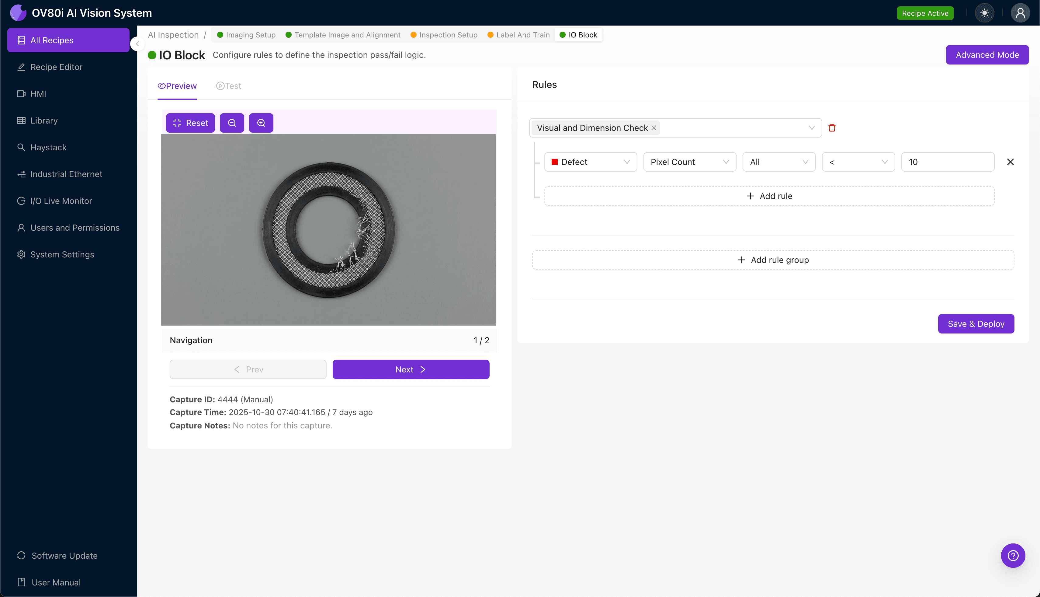
"Torn conductive layers in connector gaskets cause EMI shielding failures and system malfunctions. AI-powered visual inspection catches micro-tears under 0.5mm that human inspectors miss, delivering consistent detection at full line speed without fatigue-related quality drops."
The Problem: Why Torn Conductive Layers Slip Through Traditional QC
Connector gaskets with conductive layers serve a critical function in electronic assemblies—providing both sealing and EMI shielding in a single component. When the conductive layer tears or degrades, the consequences range from signal interference to complete system failure in the field.
Common Defects Found in Connector Gaskets with Conductive Layers:
- Micro-tears in the conductive coating — hairline fractures that compromise shielding effectiveness
- Delamination at layer boundaries — separation between the conductive layer and substrate material
- Abrasion damage from handling — surface scratches that break continuity in the conductive path
- Incomplete conductive coverage — gaps or voids in the coating application process
- Edge lifting or peeling — conductive layer separating at gasket perimeters
- Stress cracking from compression set — fractures caused by repeated gasket compression cycles
Human inspectors struggle with these defects because many tears measure less than 0.5mm and blend into the gasket's natural surface texture. Inspector fatigue compounds the problem—after hours of examining dark-colored gaskets under magnification, detection rates can drop by 30% or more.
The Solution: Machine Vision + Deep Learning
AI-powered visual inspection eliminates the variability inherent in human quality control. Deep learning models excel at detecting subtle pattern disruptions in conductive coatings—identifying defects that would be invisible to even the most experienced inspector.
Overview.ai's approach delivers consistent, objective inspection at full line speed. The system never fatigues, never second-guesses itself, and documents every inspection decision with complete traceability.
Step 1: Imaging Setup
Position the connector gasket with the conductive layer facing upward under the OV80i camera. The conductive surface should be fully visible within the field of view, with consistent lighting to reveal subtle surface variations.
Click "Configure Imaging" in the Overview interface. Adjust Camera Settings—increase exposure slightly to capture detail in darker conductive coatings, and fine-tune gain to enhance contrast at tear edges.
Click "Save" to lock in your optimized imaging parameters.
Step 2: Image Alignment
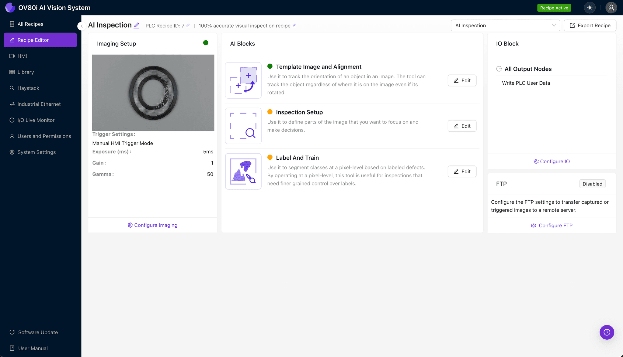
Navigate to the "Template Image" tab and capture a Template of a known-good gasket. This reference image ensures consistent part positioning across all inspections.
Click "+ Rectangle" and draw a region around the main gasket body, encompassing the entire conductive layer surface. Set the "Rotation Range" to 20 degrees to accommodate normal variation in part orientation on the line.
Step 3: Inspection Region Selection
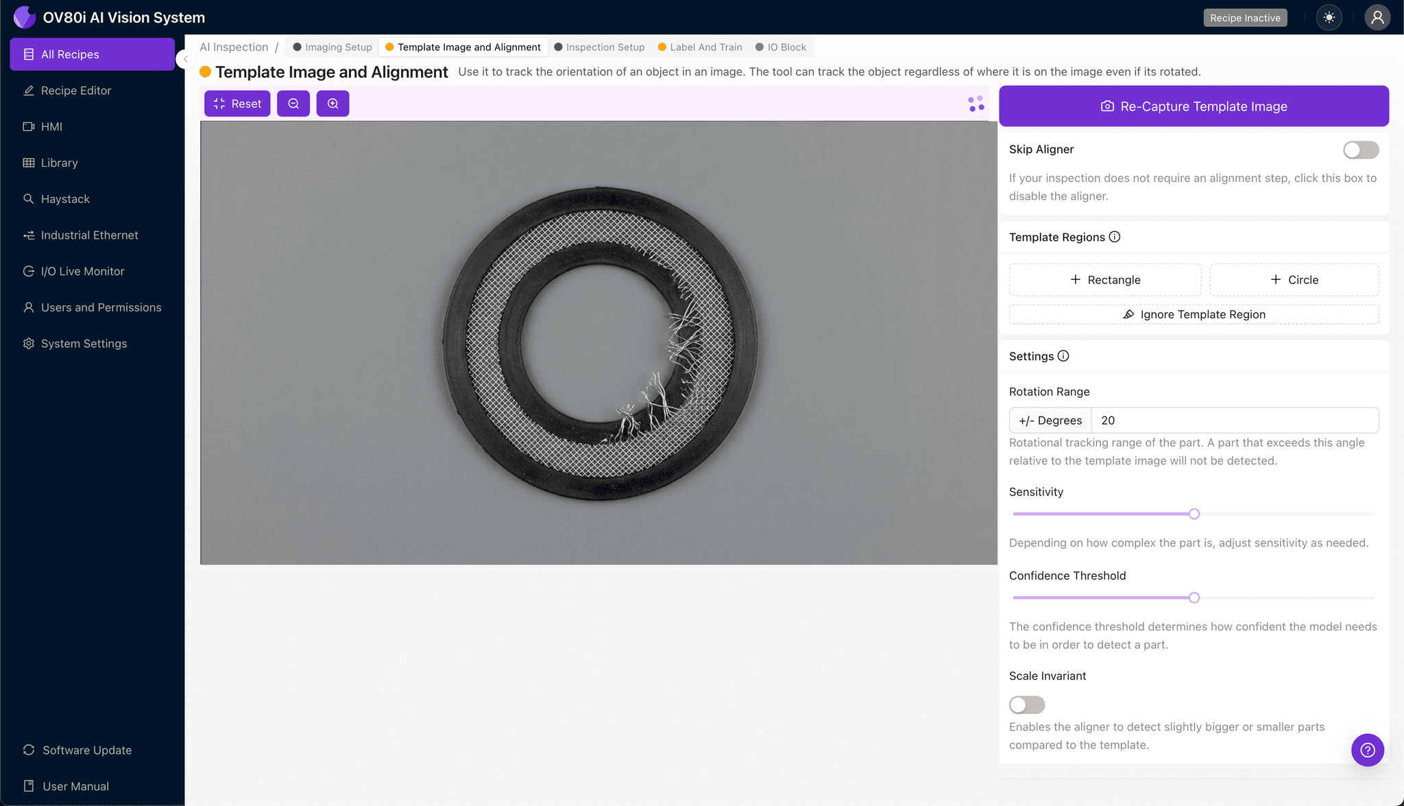
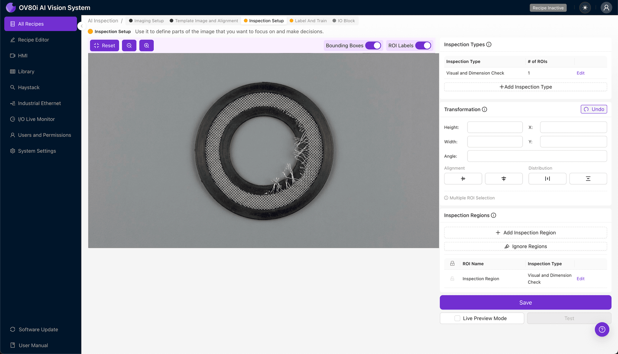
Navigate to "Inspection Setup" to define where the system should look for defects. Rename your "Inspection Types" to descriptive labels like "Conductive_Layer_Tear" or "Edge_Delamination" for clear reporting.
Click "+ Add Inspection Region" to create your first zone. Resize the yellow box to cover the critical conductive surface area—pay special attention to edges and corners where tears most commonly originate.
Click "Save" after defining all inspection regions.
Step 4: Labeling Data
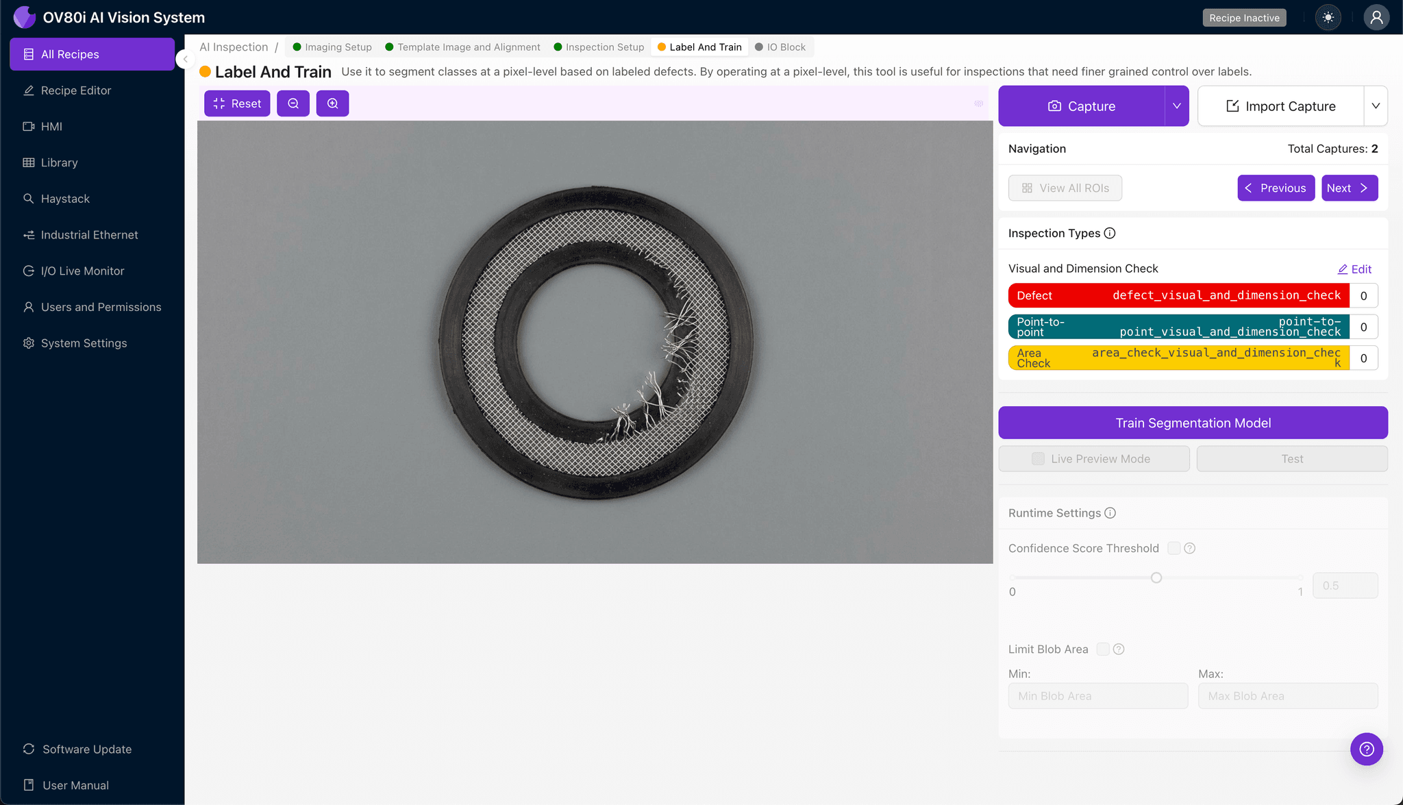
This human-in-the-loop phase trains the AI to recognize defects specific to your gaskets. Review captured images and label each as Good or Bad based on your quality standards.
Include representative samples across your full production range—different gasket sizes, material lots, and lighting conditions. Add known failure modes from your reject history to ensure the model learns from real-world defect examples.
Step 5: Creating Rules
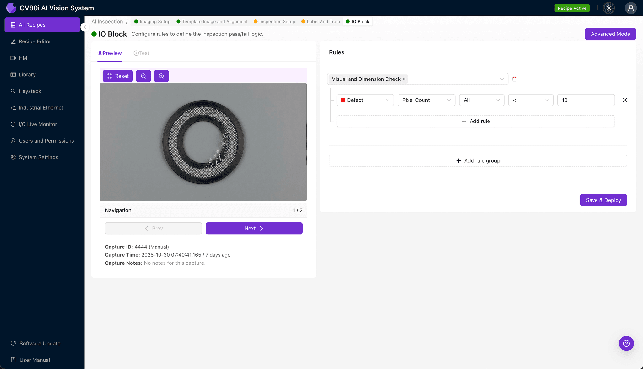
Set your pass/fail logic based on the Inspection Types you defined earlier. For conductive layer integrity, you might configure the system to reject any gasket where tear confidence exceeds 85%.
Gate automated acceptance directly on the line—parts passing inspection continue to packaging while flagged units divert to secondary review or scrap. This closed-loop approach ensures zero suspect parts reach your customer.
Key Outcomes & ROI
Manufacturers implementing AI-powered inspection for connector gaskets consistently report measurable improvements:
- Reduced scrap rates — catch defects earlier in the process before value-add operations
- Higher throughput — inspect 100% of parts at line speed without bottlenecks
- Enhanced compliance and traceability — maintain complete inspection records for automotive, aerospace, and medical audits
- Process improvement insights — identify upstream issues causing conductive layer failures through defect trend analysis
Eliminate Conductive Layer Defects Today
Stop relying on fatigued inspectors to catch microscopic tears. Deploy Overview.ai to detect conductive layer defects instantly at full line speed.