
Detecting Cracked Traces in Flexible Printed Circuits: A Complete Visual Inspection Guide
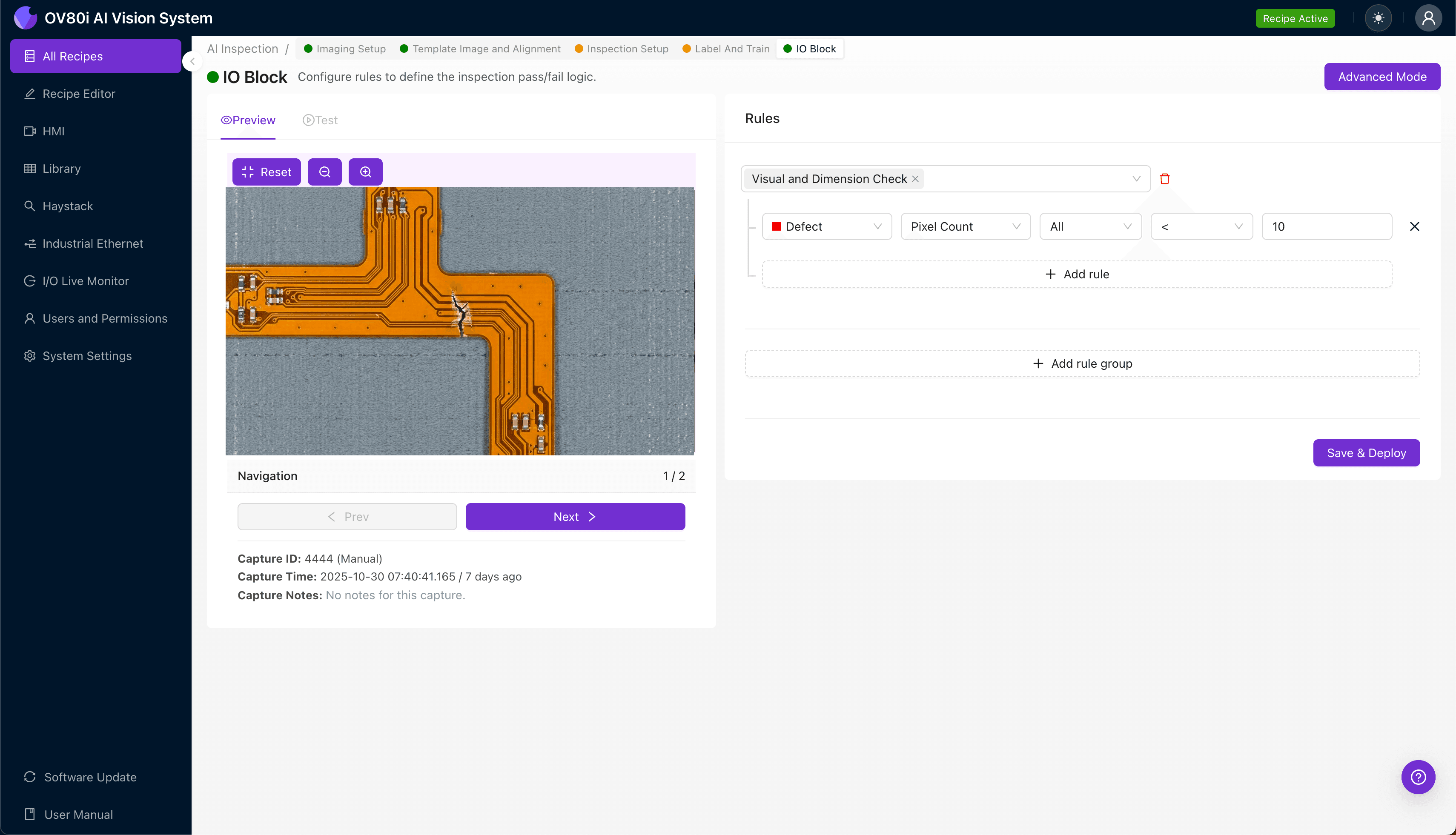
"Cracked traces at FPC bend zones are among the most costly and difficult-to-detect failure modes in electronics manufacturing. Deep learning-powered visual inspection catches microscopic fractures that human inspectors miss, ensuring 100% quality at full production speed."
The Problem: Why Cracked Traces at FPC Bends Are a Silent Killer in Electronics Manufacturing
Flexible printed circuits are the backbone of modern compact electronics, from smartphones to medical devices. However, their greatest strength—flexibility—is also their greatest vulnerability, with cracked traces at bend zones representing one of the most costly and difficult-to-detect failure modes in FPC production.
Common Defects Found in FPC Cracked Trace Failures:
- Hairline fractures — Microscopic cracks that propagate under repeated flexing or thermal stress
- Complete trace separation — Full breaks in the copper conductor causing open circuits
- Partial delamination — Copper lifting from the polyimide substrate near bend radii
- Crazing patterns — Network of fine surface cracks indicating material fatigue
- Solder mask micro-cracking — Protective layer damage exposing traces to oxidation
- Stress whitening — Visual indicator of substrate damage preceding trace failure
Human inspectors struggle to catch these defects consistently. Fatigue sets in quickly when examining repetitive bend zones, and the microscopic nature of early-stage cracks makes them nearly invisible to the naked eye—especially at production speeds exceeding hundreds of units per hour.
The Solution: Machine Vision and Deep Learning for FPC Inspection
Traditional rule-based vision systems fail with FPC inspection because cracked traces don't follow predictable patterns. The cracks vary in orientation, size, and location depending on bend radius, material batch, and manufacturing conditions. Deep learning models excel here because they learn the subtle visual signatures of damage rather than relying on rigid geometric rules.
Overview.ai's approach delivers consistent, objective inspection at full line speed. The OV80i system captures high-resolution images of every FPC, analyzing bend zones in milliseconds while maintaining the accuracy that would require a team of expert inspectors working at an unsustainable pace.
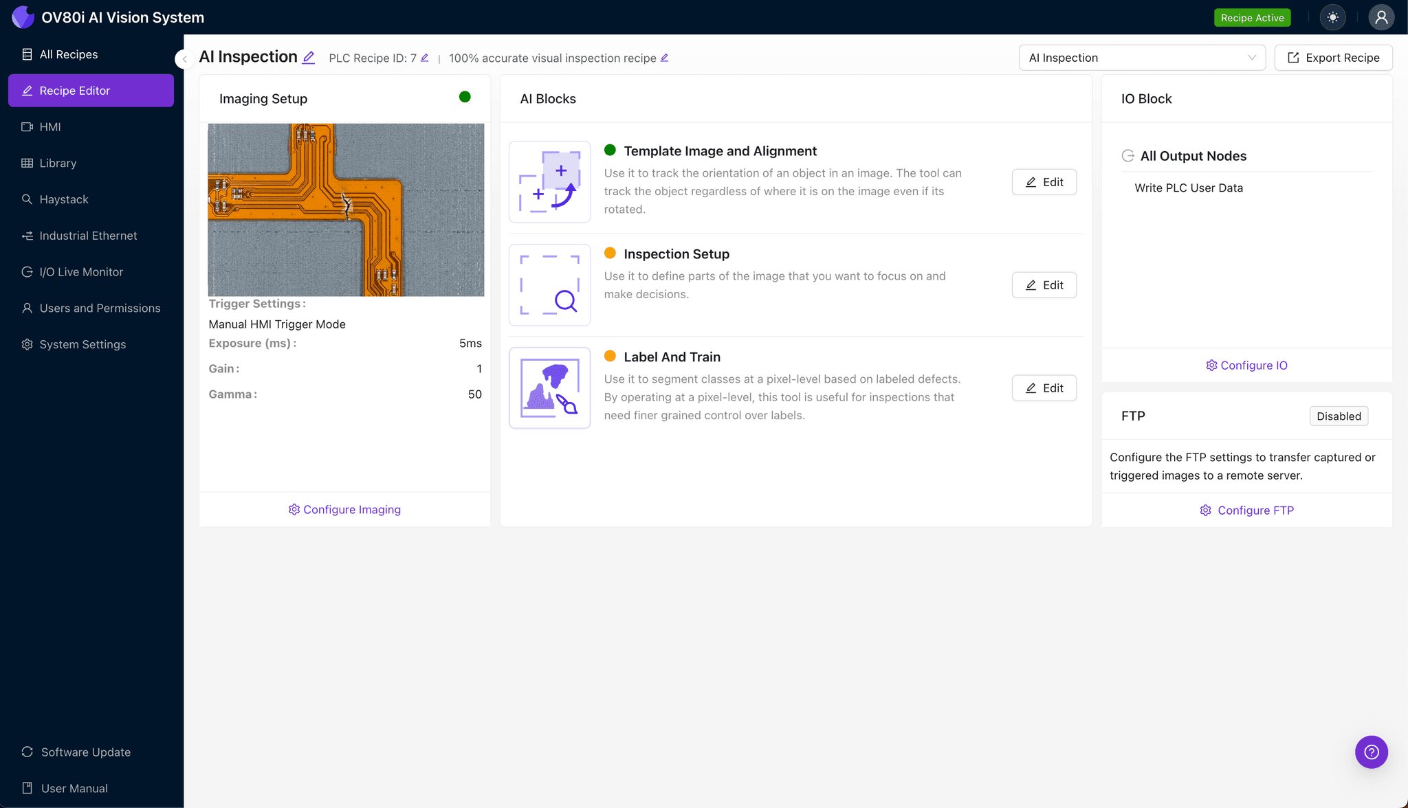
Step 1: Imaging Setup
Position the FPC sample under the OV80i camera with the bend zone clearly visible and properly illuminated. Angled lighting often works best for revealing hairline cracks that appear invisible under diffuse illumination.
Click "Configure Imaging" in the Overview interface. Adjust Camera Settings including exposure time and gain to maximize contrast between intact traces and damaged areas.
Click "Save" once the cracked trace defects are clearly distinguishable from good traces in your live preview.
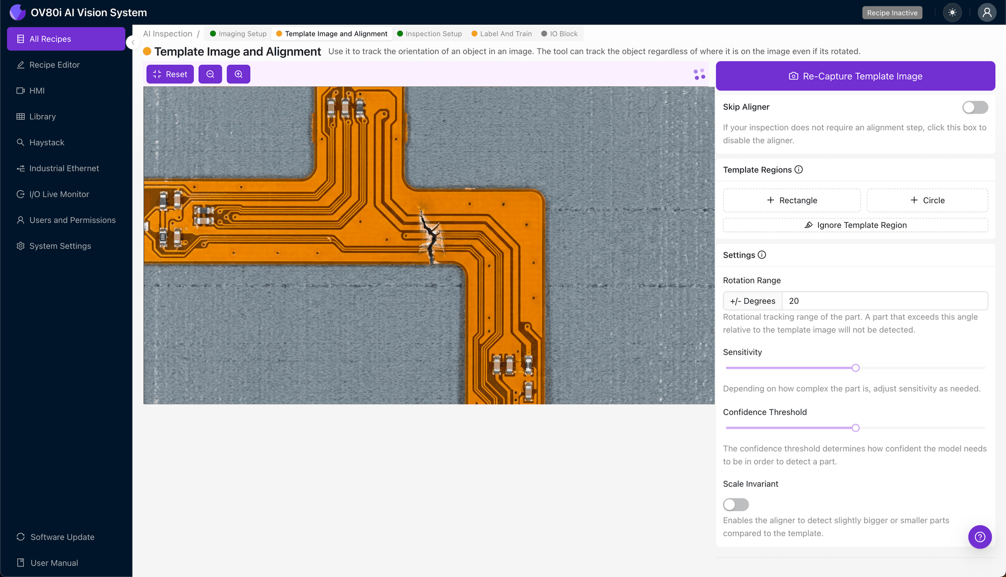
Step 2: Image Alignment
Navigate to "Template Image" in the configuration menu. Capture a Template image of a representative FPC in its standard orientation.
Click "+ Rectangle" to add an alignment region around the main body of the circuit. Focus on stable reference features like mounting holes or edge geometry rather than the flexible bend zone itself.
Set "Rotation Range" to 20 degrees to accommodate normal variation in part placement on your conveyor or fixture.
Step 3: Inspection Region Selection
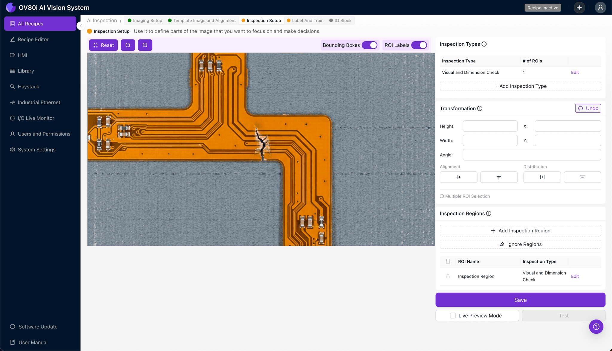
Navigate to "Inspection Setup" from the main dashboard. Rename your "Inspection Types" to reflect your specific defect categories—for example, "Bend_Zone_Crack" or "Trace_Fracture."
Click "+ Add Inspection Region" to create a new detection zone. Resize the yellow bounding box to cover the critical bend radius area where trace cracking is most likely to occur.
Click "Save" after confirming the region captures the full extent of potential defect locations across your part variation.
Step 4: Labeling Data
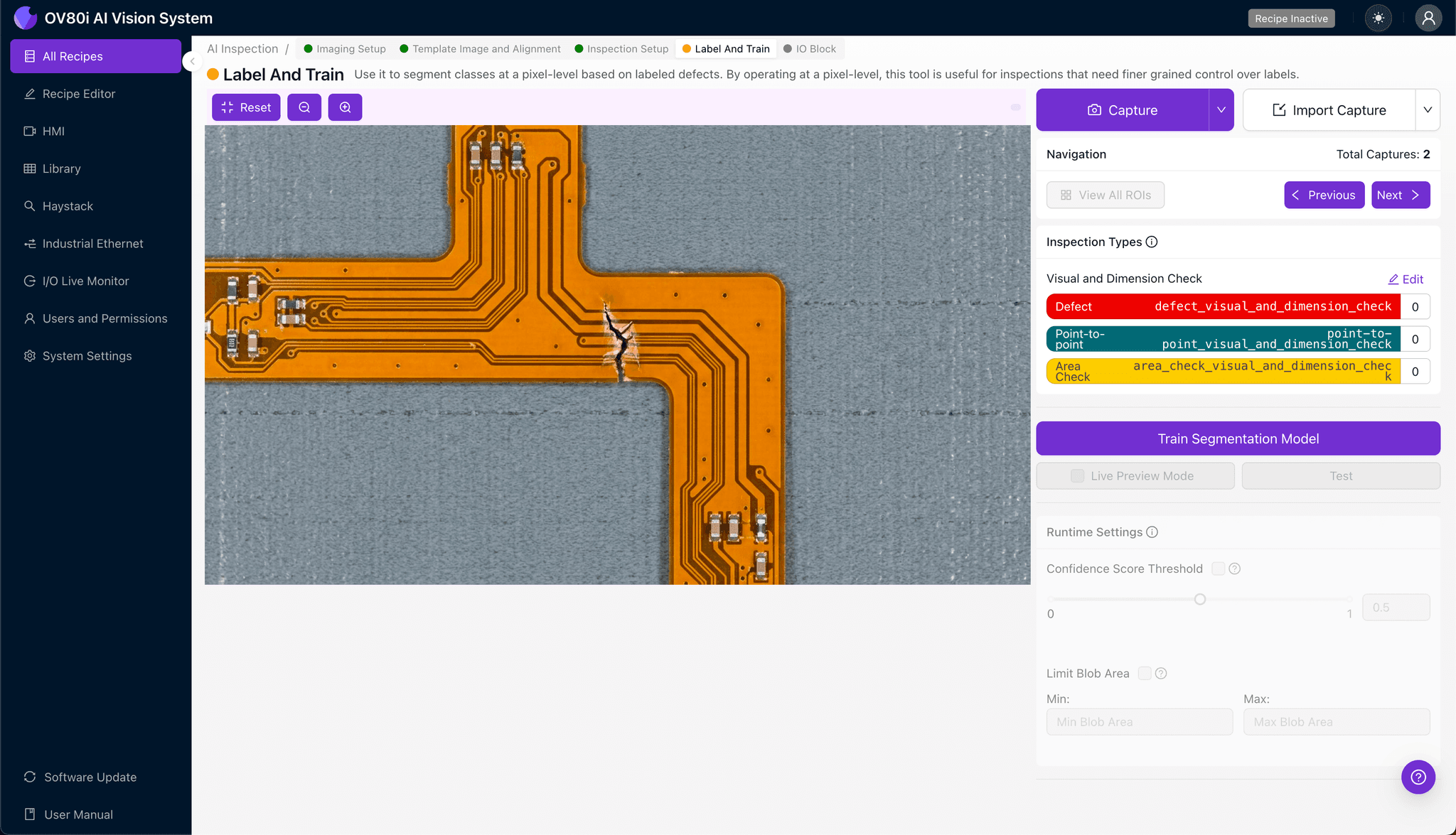
This is where human expertise trains the AI system. Inspectors review captured images and label each as Good or Bad, teaching the deep learning model what acceptable and defective parts look like.
Include representative samples across your full range of variation. Label obvious failures, borderline cases, and known failure modes from your quality history.
The more diverse your labeled dataset, the more robust your inspection model becomes. Aim for at least 50-100 examples of each defect type for initial training.
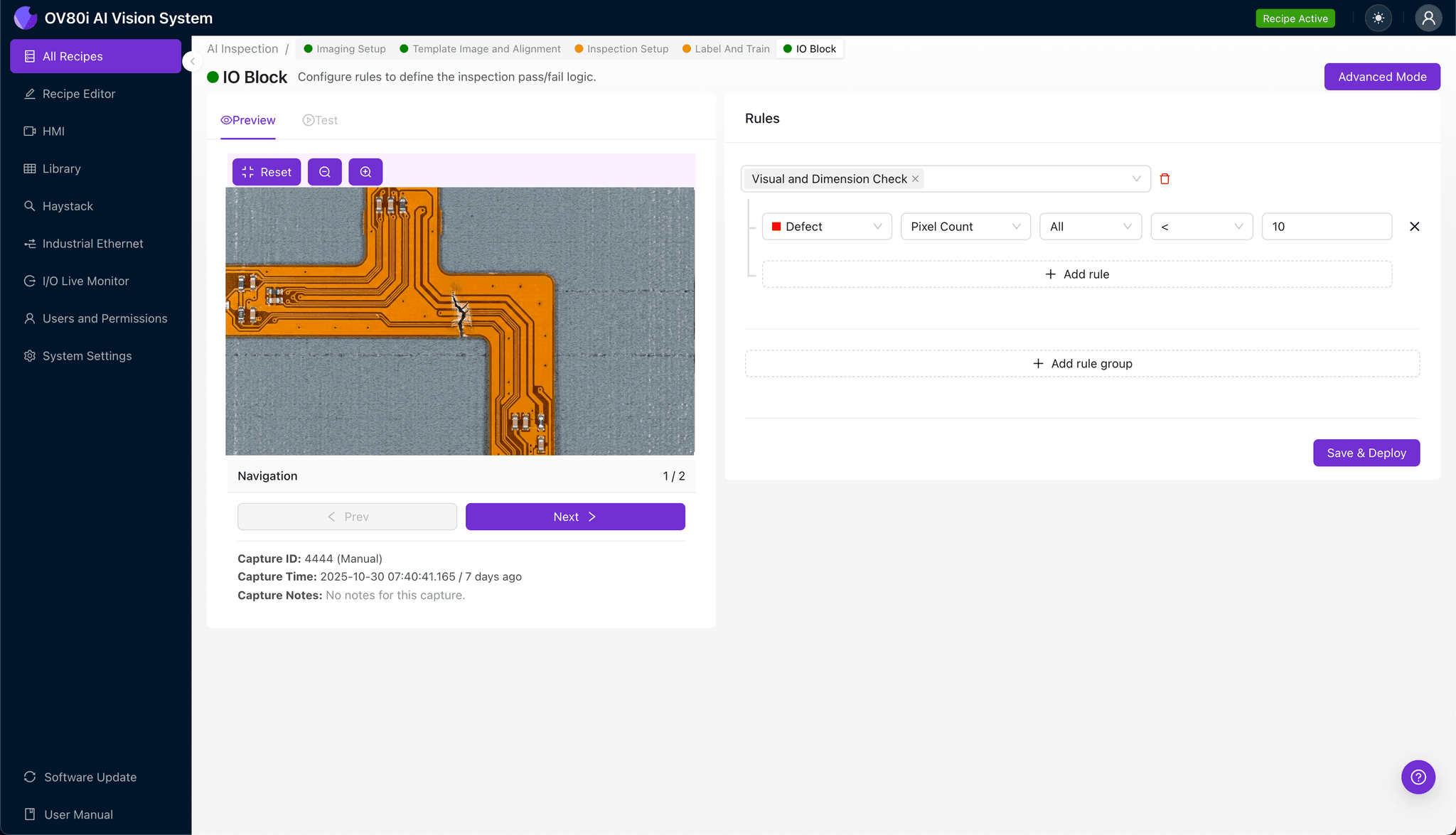
Step 5: Creating Rules
Set your pass/fail logic based on the Inspection Types you've defined. Determine whether a single detected crack triggers rejection or whether you need confidence thresholds for borderline cases.
Gate automated acceptance on the line by connecting inspection results to your reject mechanism. Parts flagged as "Bad" route automatically to quarantine while "Good" parts continue downstream without operator intervention.
Key Outcomes & ROI
Implementing automated visual inspection for FPC cracked trace detection delivers measurable business impact:
- Reduced scrap rates — Catch cracked traces before assembly into expensive finished goods, preventing costly rework and field failures
- Higher throughput — Inspect 100% of production at line speed without bottlenecking on manual inspection stations
- Compliance and traceability — Maintain complete inspection records with timestamped images for automotive, medical, and aerospace quality requirements
- Process improvement insights — Analyze defect trends to identify upstream issues like tooling wear, material inconsistencies, or handling damage
Start Detecting FPC Defects Today
Cracked traces at bend zones don't have to be a hidden quality risk. Deploy Overview.ai to catch defects instantly with consistent, objective detection.