High-Speed Test Fixture with Excessive Insertion Loss: A Complete Visual Inspection Guide
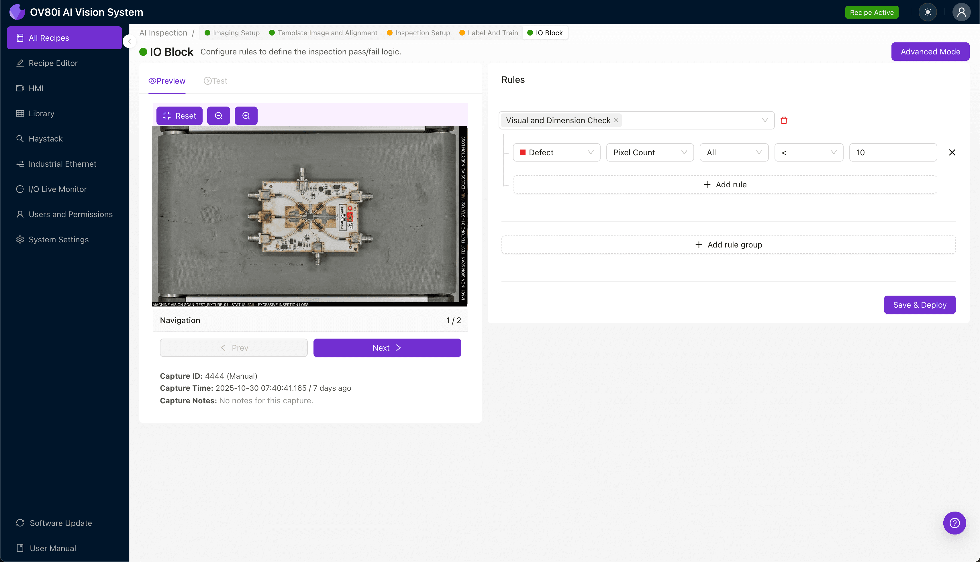
"Excessive insertion loss in high-speed test fixtures causes false test failures and masks real defects. AI-powered visual inspection catches worn contacts, contamination, and connector damage before they impact production—delivering consistent, objective quality control at line speed."
The Problem: Why Insertion Loss Defects Slip Through Manual Inspection
High-speed test fixtures are critical components in electronics manufacturing, serving as the interface between your device under test (DUT) and automated test equipment. When these fixtures develop excessive insertion loss, they can cause false test failures, mask real defects, and bring production lines to a grinding halt.
Common defects contributing to excessive insertion loss include:
- Worn or damaged contact pins – Bent, pitted, or oxidized probe tips that degrade signal integrity
- Contaminated contact surfaces – Solder paste residue, flux buildup, or particulate debris on critical interfaces
- Cracked or delaminated PCB traces – Hairline fractures in the fixture's internal signal pathways
- Loose or damaged RF connectors – SMA or coaxial connections with worn threads or damaged center conductors
- Impedance discontinuities – Solder joint anomalies or via defects causing signal reflections
- Cable and interconnect degradation – Kinked, stretched, or abraded coaxial cables within the fixture assembly
Manual inspection of these fixtures is notoriously unreliable. Inspectors face microscopic defect sizes, repetitive fatigue across hundreds of contact points, and the challenge of maintaining consistency across multiple shifts—resulting in escaped defects that only surface as costly test failures downstream.
The Solution: AI-Powered Visual Inspection for Test Fixtures
Machine vision combined with deep learning transforms test fixture inspection from a subjective, error-prone process into a consistent, data-driven quality gate. Unlike rule-based systems that struggle with the subtle variations in contact wear and surface contamination, AI models learn to identify the full spectrum of defect patterns from real production data.
Overview.ai's approach delivers consistent, objective inspection at line speed—examining every fixture with the same precision on unit one as on unit one thousand. The OV80i system captures high-resolution imagery and applies trained neural networks to detect defects that would escape even the most experienced human inspector.
Step 1: Imaging Setup
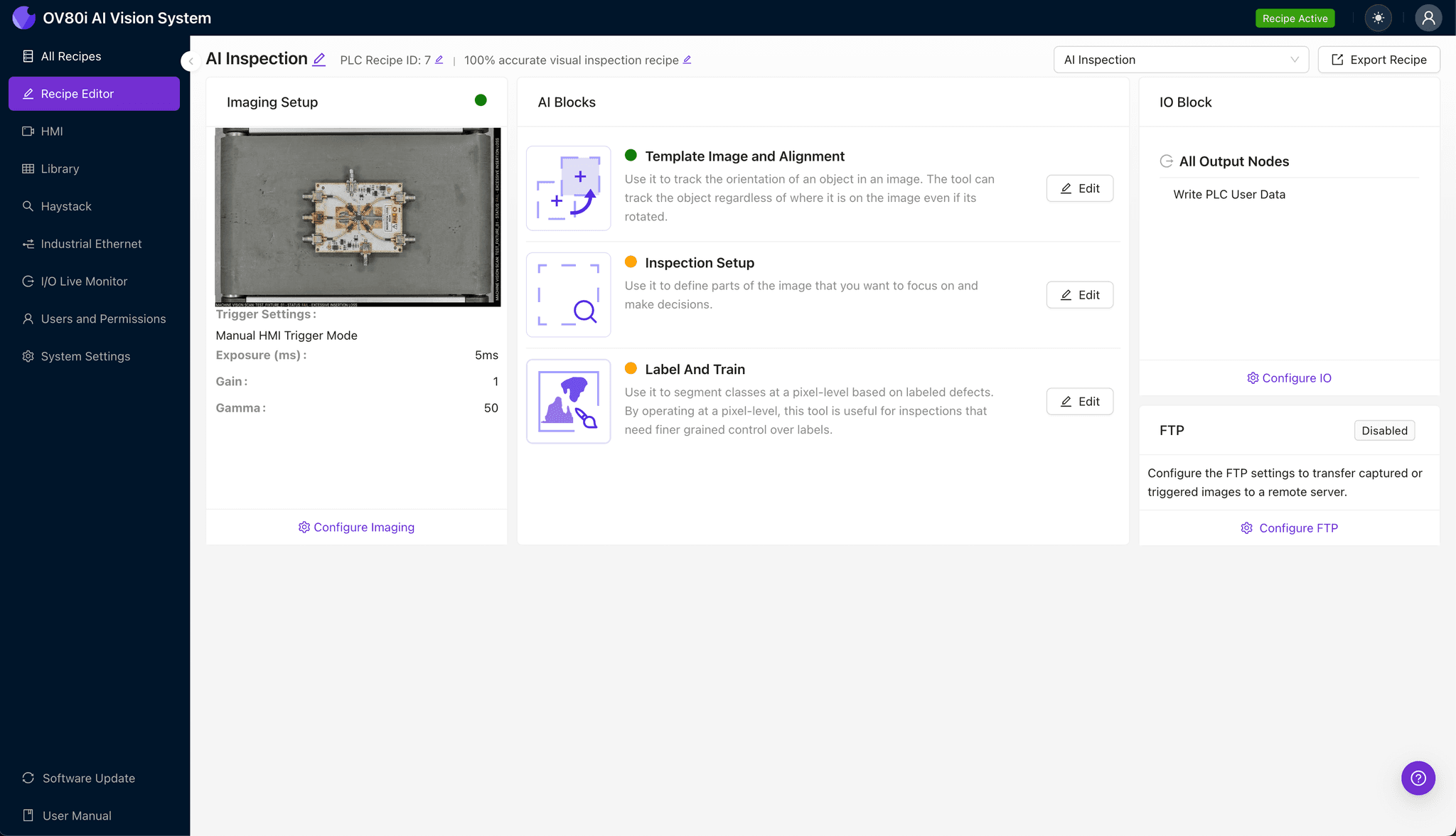
Position the high-speed test fixture under the OV80i camera system, ensuring the contact array and connector interfaces are fully visible in the field of view. Proper lighting is essential—use angled illumination to reveal surface defects on reflective pin surfaces.
Click "Configure Imaging" to access the Camera Settings panel. Adjust exposure to capture detail in both bright metallic surfaces and darker PCB substrates, then fine-tune gain to minimize noise while maintaining defect visibility.
Click "Save" to lock in your imaging configuration.
Step 2: Image Alignment
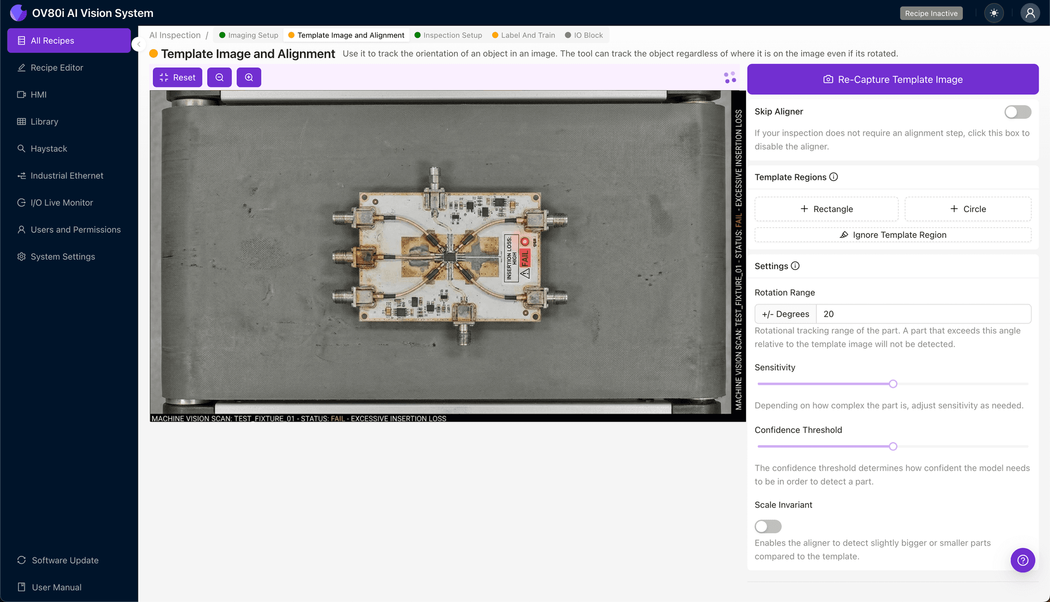
Navigate to the "Template Image" section and capture a Template of your golden reference fixture. This template establishes the baseline for consistent part-to-part alignment.
Click "+ Rectangle" to add an alignment region around the main body of the fixture—typically the outer frame or a distinctive feature like the connector block. Set the "Rotation Range" to 20 degrees to accommodate minor variations in how fixtures are presented to the camera.
Step 3: Inspection Region Selection
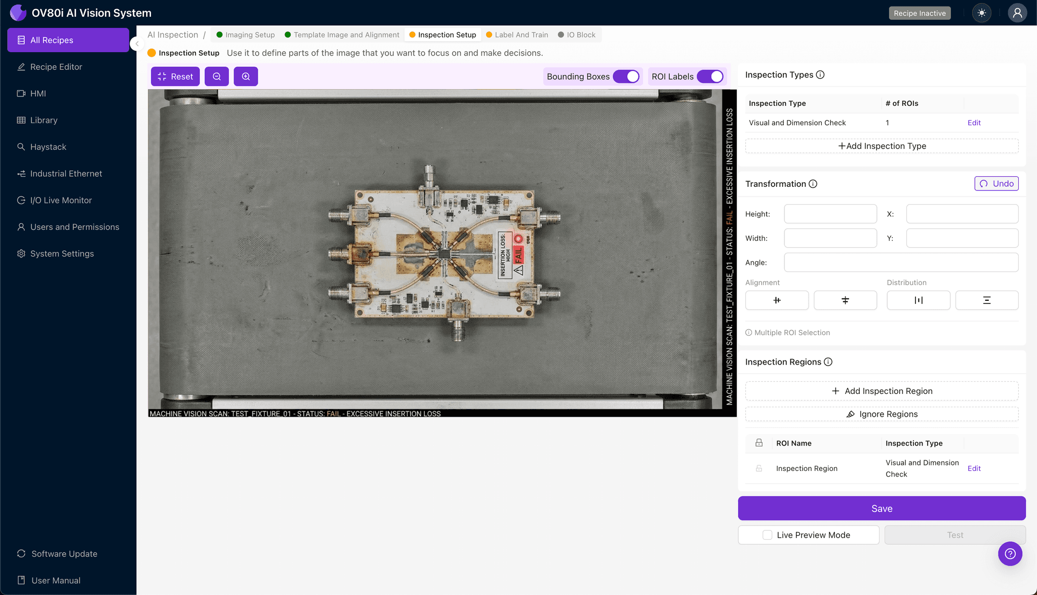
Navigate to "Inspection Setup" to define where the AI should focus its analysis. Rename your "Inspection Types" to reflect the specific defect categories—for example, "Contact Pin Wear," "Connector Damage," and "Surface Contamination."
Click "+ Add Inspection Region" to create targeted zones. Resize the yellow bounding box over critical defect areas: the probe tip contact surfaces, RF connector interfaces, and high-density signal trace regions.
Click "Save" to finalize your inspection configuration.
Step 4: Labeling Data
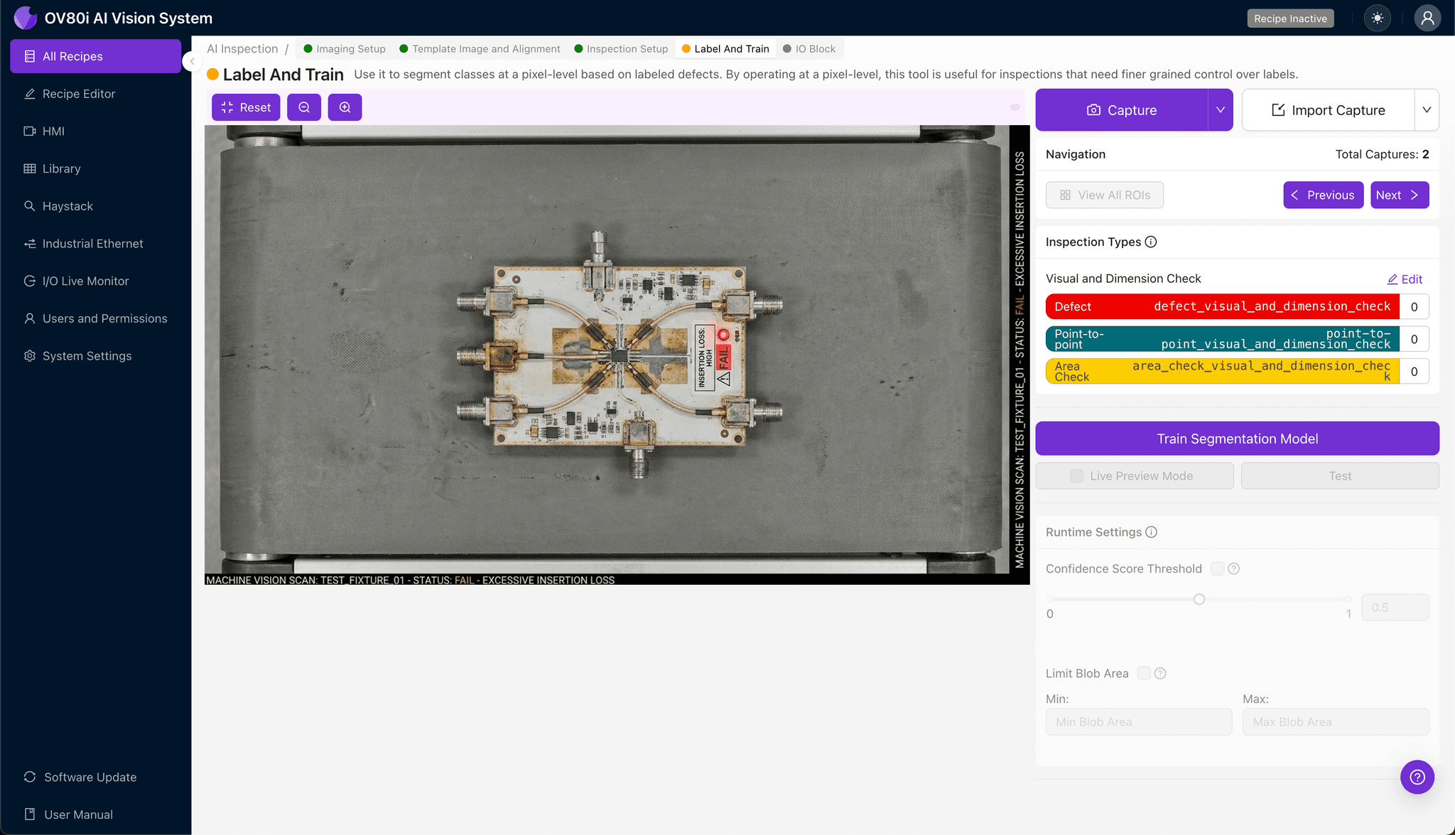
The human-in-the-loop labeling process is where your team's expertise trains the AI model. Production operators and quality engineers review captured images and classify them as Good or Bad based on established acceptance criteria.
Include representative samples across the full range of acceptable variation, along with known failure modes like oxidized contacts, bent pins, and contaminated surfaces. The more diverse your labeled dataset, the more robust your trained model will perform in production.
Step 5: Creating Rules
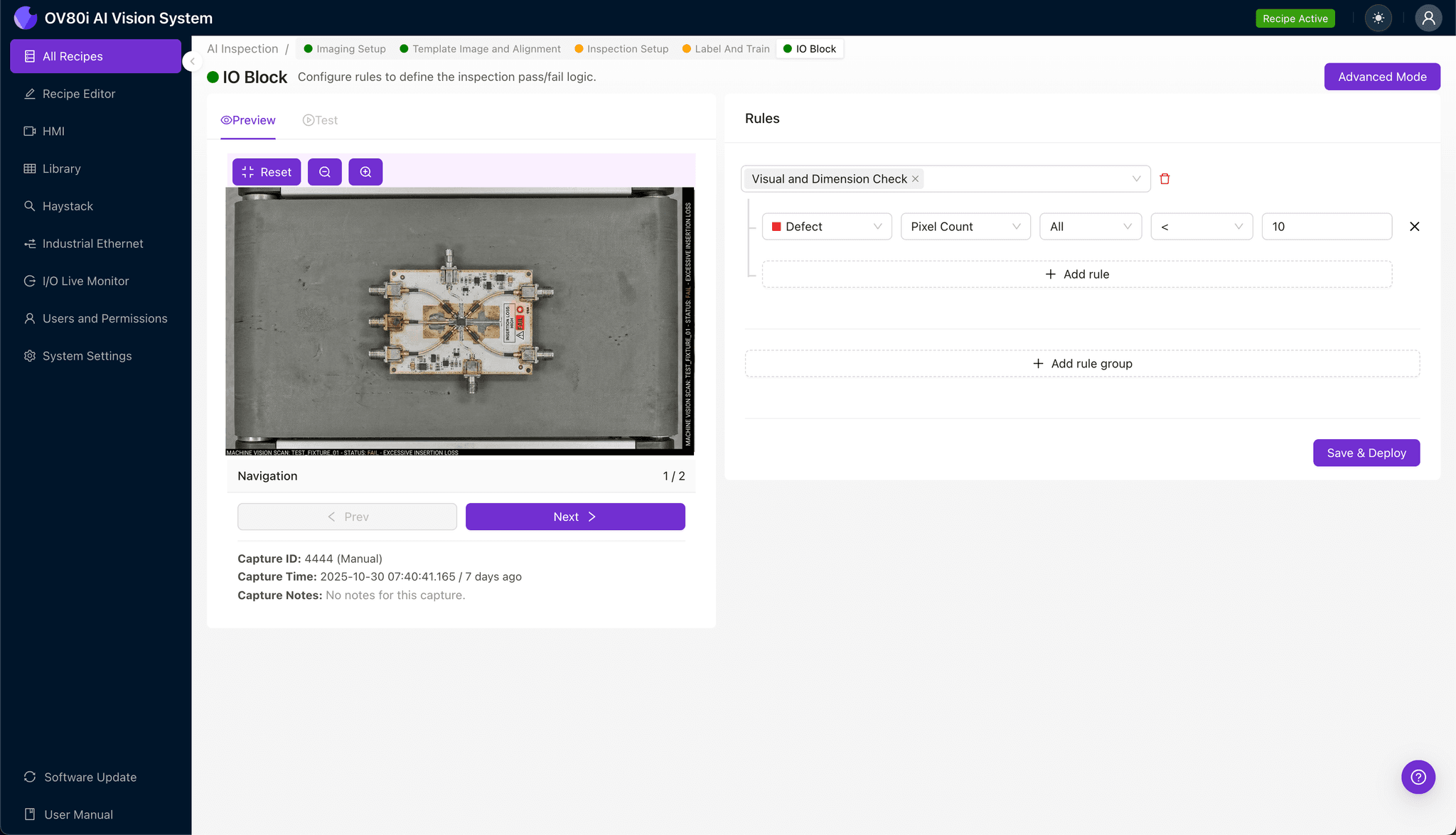
Set your pass/fail logic based on the Inspection Types you defined earlier. Configure thresholds that align with your quality specifications—for instance, flagging any fixture with detected contact wear for immediate removal from service.
These rules gate automated acceptance on the line, ensuring that only fixtures meeting your insertion loss requirements continue to test stations. Rejected fixtures route automatically to rework or replacement queues.
Key Outcomes & ROI
Implementing AI-powered visual inspection for your high-speed test fixtures delivers measurable business impact:
- Reduced scrap and rework – Catch fixture degradation before it causes false DUT failures and wasted product
- Higher throughput – Eliminate inspection bottlenecks with automated, at-speed quality gates
- Enhanced compliance and traceability – Maintain complete inspection records with timestamped imagery for audit and root cause analysis
- Process improvement insights – Identify fixture wear patterns and optimize preventive maintenance schedules based on real defect data
Conclusion
Excessive insertion loss in high-speed test fixtures doesn't have to be a hidden source of yield loss and test escapes. With Overview.ai's visual inspection platform, manufacturers gain the consistent, objective quality control needed to keep test operations running at peak efficiency.
Ready to eliminate fixture-related test failures? Contact Overview.ai to schedule a demonstration with your actual production fixtures.
Eliminate Test Fixture Defects Today
Stop relying on manual inspection. Deploy Overview.ai to catch insertion loss defects instantly and keep your test lines running.