How to Detect Mated Pair with Galvanic Mismatch Defects Using AI-Powered Visual Inspection
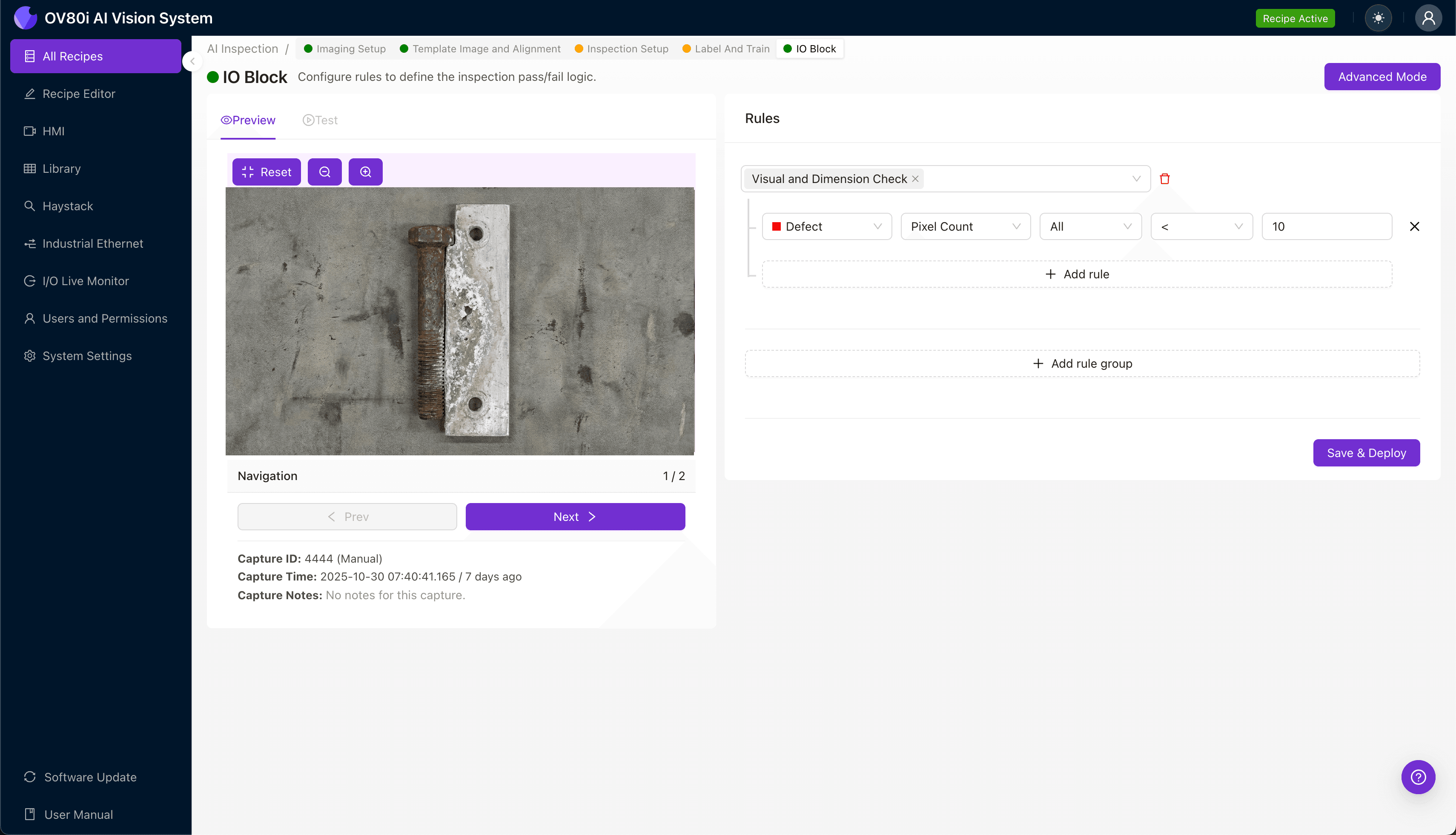
"Galvanic mismatch in mated pair assemblies causes accelerated corrosion and field failures that human inspectors often miss. AI-powered visual inspection with the OV80i system detects subtle oxidation, pitting, and plating defects at production speed with 100% consistency."
The Problem: Why Galvanic Mismatch in Mated Pairs Is a Critical Quality Challenge
When two dissimilar metals are joined in an electrical connector or fastener assembly, galvanic mismatch creates a ticking time bomb for product reliability. This electrochemical incompatibility accelerates corrosion, degrades conductivity, and ultimately leads to field failures that damage both customer relationships and your bottom line.
Common Defects Found in Mated Pairs with Galvanic Mismatch:
- Surface discoloration or oxidation at the contact interface between dissimilar metals
- White powdery residue (aluminum oxide) forming around aluminum-to-copper joints
- Pitting corrosion on the anodic (less noble) metal surface
- Fretting wear marks caused by micro-motion between galvanically incompatible surfaces
- Improper plating coverage exposing base metal to galvanic attack
- Contamination or debris in the mating zone that accelerates electrochemical reactions
Human inspectors struggle to catch these defects consistently. Subtle discoloration and early-stage pitting are easy to miss after hours on the line, and the pressure to maintain throughput means borderline parts often pass unchecked.
The Solution: Machine Vision + Deep Learning for Consistent Detection
AI-powered visual inspection eliminates the variability inherent in human judgment. Deep learning models trained on thousands of labeled images learn to recognize the subtle visual signatures of galvanic mismatch—patterns that would escape even experienced quality technicians working at production speeds.
Overview.ai's approach delivers consistent, objective, at-line-speed inspection that never fatigues and never compromises. The OV80i system integrates directly into your production workflow, inspecting 100% of mated pair assemblies while providing real-time pass/fail decisions and full traceability.
Step 1: Imaging Setup
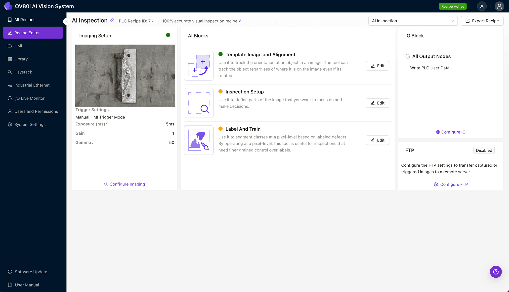
Position the mated pair assembly under the OV80i camera, ensuring the contact interface between the two metals is clearly visible. Proper lighting is essential—angled illumination often reveals surface oxidation and discoloration more effectively than direct lighting.
Click "Configure Imaging" to access the Camera Settings panel. Adjust exposure to prevent washout on reflective plating surfaces, and fine-tune gain to capture subtle color variations that indicate early galvanic activity.
Click "Save" to lock in your imaging configuration.
Step 2: Image Alignment
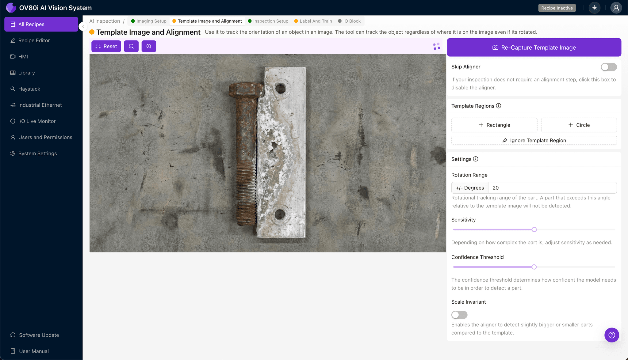
Navigate to the "Template Image" section and capture a Template of your golden sample mated pair. This reference image anchors the system's understanding of proper part positioning.
Click "+ Rectangle" to add a region around the main body of the connector assembly. This tells the system where to look for the part in each frame.
Set "Rotation Range" to 20 degrees to accommodate minor variation in how parts present on the line.
Step 3: Inspection Region Selection
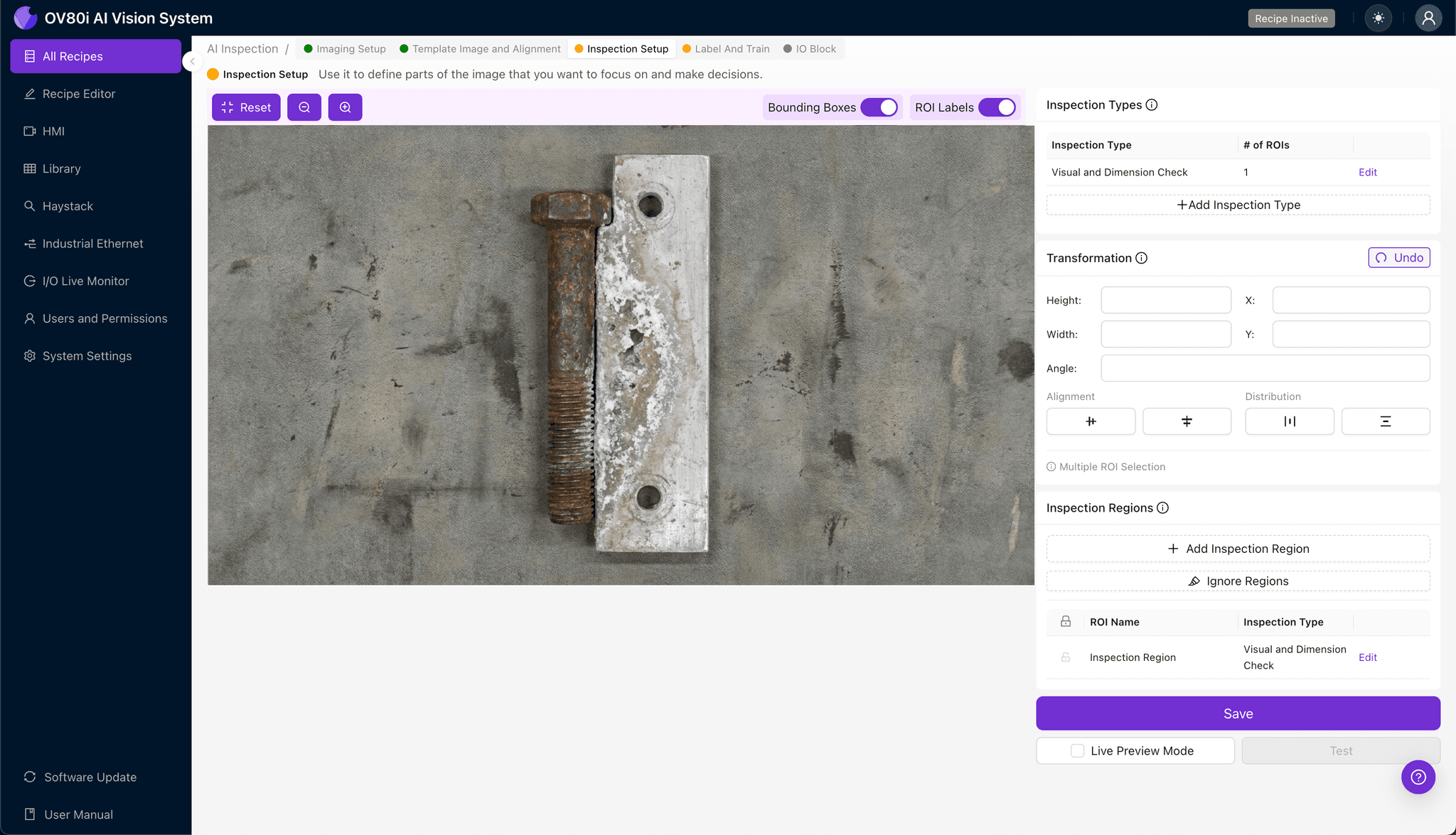
Navigate to "Inspection Setup" to define exactly where defects matter most. Rename your "Inspection Types" to reflect the specific failure modes you're targeting—for example, "Contact Zone Oxidation" or "Plating Integrity."
Click "+ Add Inspection Region" to create your first detection zone. Resize the yellow bounding box to cover the critical contact interface where galvanic mismatch manifests.
Add additional regions for secondary inspection areas, such as plating boundaries or fastener threads. Click "Save" when all critical zones are defined.
Step 4: Labeling Data
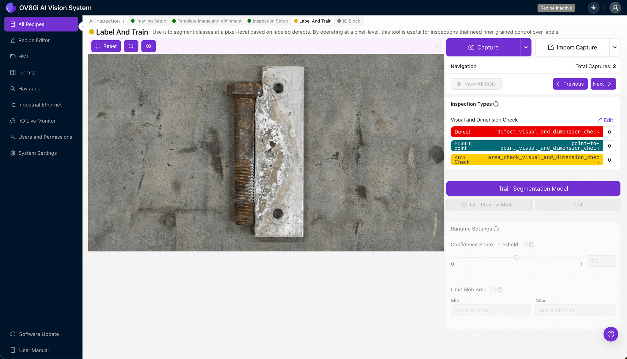
The human-in-the-loop labeling process is where your quality expertise trains the AI. Review incoming images and label each as Good (acceptable mated pair) or Bad (galvanic mismatch present).
Include representative samples across the full spectrum of production variation—different lighting conditions, slight positional shifts, and varying degrees of acceptable surface finish. Most importantly, incorporate known failure modes: confirmed oxidation, documented pitting, and verified plating failures from your reject bins.
Step 5: Creating Rules
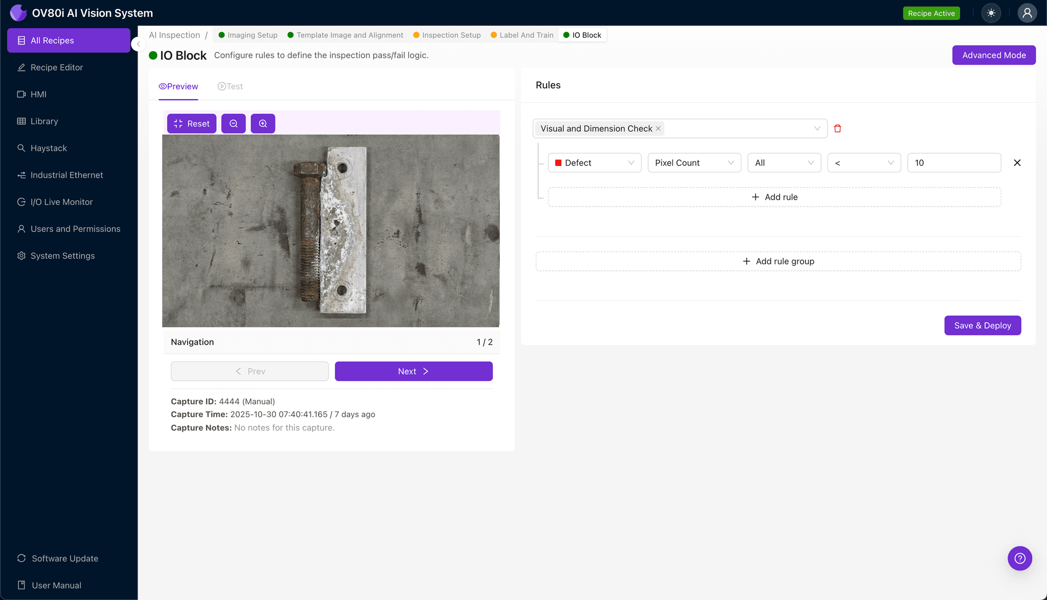
With your model trained, navigate to the Rules section to set pass/fail logic based on your defined Inspection Types. Configure confidence thresholds that balance escape rate against false reject rate for your specific tolerance requirements.
Gate automated acceptance on the line by connecting these rules to your reject mechanism—diverter, robotic arm, or line stop. Parts that fail inspection are automatically segregated for review or rework.
Key Outcomes & ROI
Implementing AI-powered inspection for mated pair galvanic mismatch delivers measurable business impact:
- Reduced scrap and rework costs by catching defective assemblies before they reach downstream processes or final assembly
- Higher throughput with 100% inline inspection that keeps pace with production—no bottleneck sampling
- Full compliance and traceability with timestamped images and inspection data for every part, supporting automotive, aerospace, and medical device audit requirements
- Process improvement insights through defect trend analysis that reveals upstream issues in plating, handling, or supplier quality
Eliminate Galvanic Mismatch Escapes Today
Overview.ai's visual inspection platform transforms how manufacturers detect and prevent galvanic compatibility issues in mated pair assemblies. Contact our team to schedule a proof-of-concept using your actual production samples.