
How to Detect a Missing Alignment Pin in MTP Connectors Using AI-Powered Visual Inspection
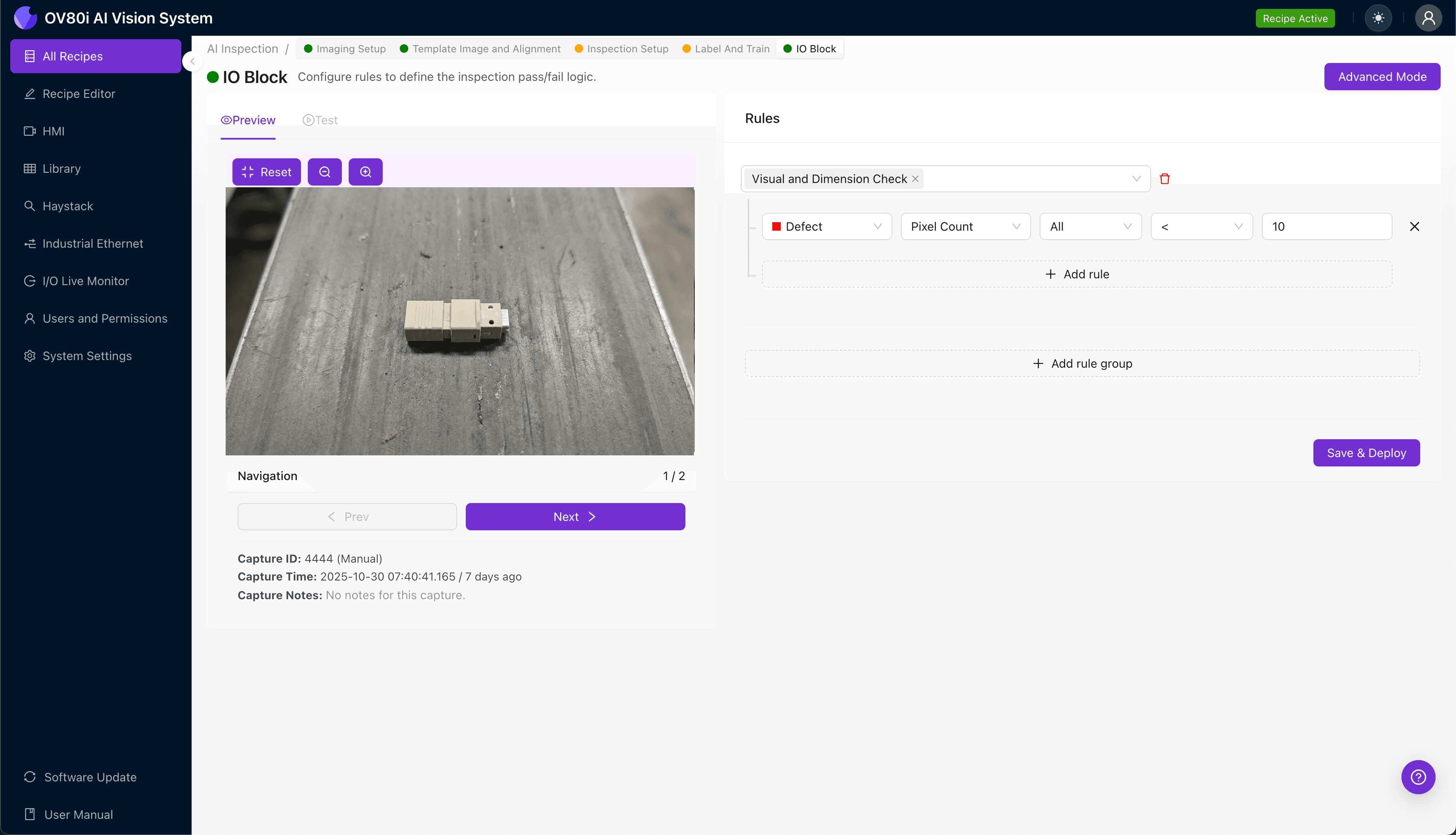
"Missing alignment pins in MTP connectors cause signal loss and network failures. AI-powered visual inspection delivers 100% inline detection at production speed, eliminating the variability of manual inspection and catching defects before they escape to customers."
The Problem: A Tiny Pin with Major Consequences
MTP connectors are the backbone of high-density fiber optic networks, and their precision alignment system is non-negotiable for signal integrity. When an alignment pin is missing, the entire connector becomes a liability—causing signal loss, return loss failures, and costly network downtime.
Common defects associated with missing alignment pins include:
- Absent guide pin — Pin completely missing from the ferrule housing
- Broken pin stub — Partial pin remnant left behind after fracture during assembly
- Incorrect pin seating depth — Pin present but not fully inserted into the ferrule bore
- Pin bore contamination — Debris or adhesive residue in the pin cavity masking absence
- Wrong pin type installed — Male/female configuration mismatch for the connector variant
- Pin angular misalignment — Pin present but tilted, indicating potential ejection risk
Manual inspection of MTP connectors is notoriously unreliable at production speeds. The alignment pins measure just 0.7mm in diameter, and inspectors examining hundreds of connectors per shift experience fatigue-induced miss rates that can exceed 5-10% by end of shift.
The Solution: Machine Vision + Deep Learning
AI-powered visual inspection eliminates the variability inherent in human inspection. Deep learning models can be trained to recognize the subtle visual signatures of missing or defective alignment pins—even when lighting conditions or connector orientations vary slightly between units.
Overview.ai's approach delivers consistent, objective inspection at full line speed. The OV80i system performs 100% inline inspection, catching defects that would otherwise escape to customers or cause downstream assembly failures.
Step 1: Imaging Setup
Position the MTP connector under the OV80i camera with the ferrule face oriented toward the lens. The alignment pin locations should be clearly visible in the field of view.
Click "Configure Imaging" in the Overview interface. Adjust the Camera Settings—increase exposure to illuminate the pin bores clearly, and fine-tune gain to enhance contrast between the metallic pins and the plastic ferrule body.
Click "Save" to lock in your imaging configuration.
Step 2: Image Alignment
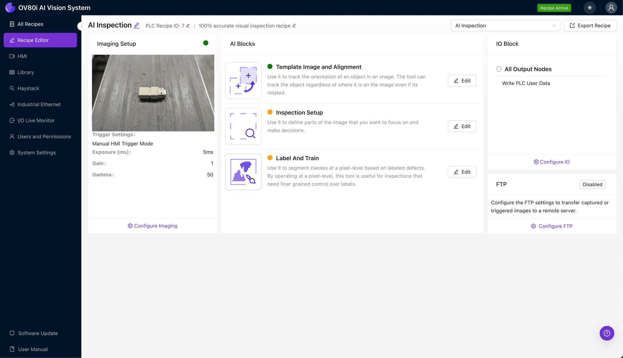
Navigate to the "Template Image" tab and capture a reference image of a properly positioned connector. This template ensures consistent alignment across all inspected units.
Click "+ Rectangle" and draw a region around the main connector body, encompassing the ferrule face and both pin locations. Set the "Rotation Range" to 20 degrees to accommodate minor orientation variations as connectors move through the inspection station.
Step 3: Inspection Region Selection
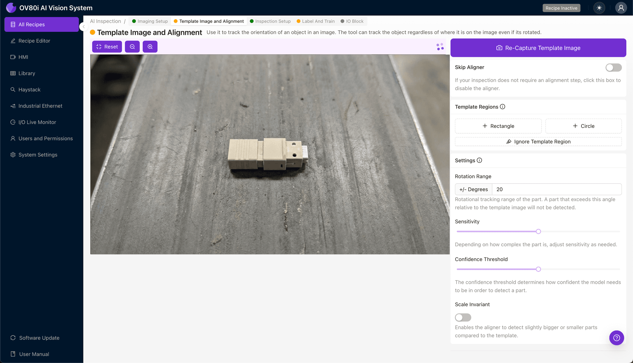
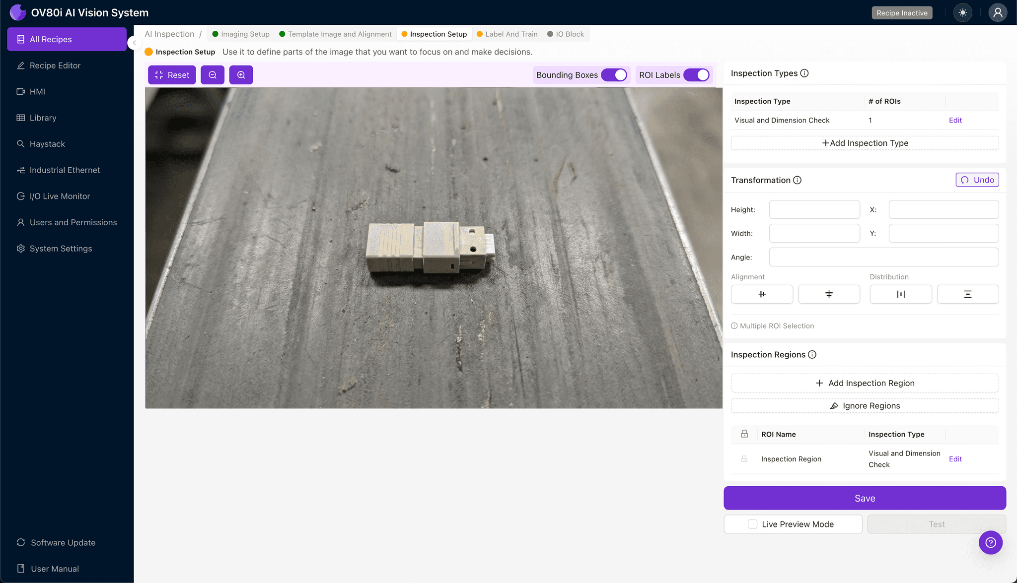
Navigate to "Inspection Setup" in the main menu. Rename your "Inspection Types" to reflect the specific checks—for example, "Left Pin Present" and "Right Pin Present."
Click "+ Add Inspection Region" for each alignment pin location. Resize the yellow bounding box to tightly frame each pin bore area, ensuring the model focuses on the critical zone without extraneous background.
Click "Save" to confirm your inspection regions.
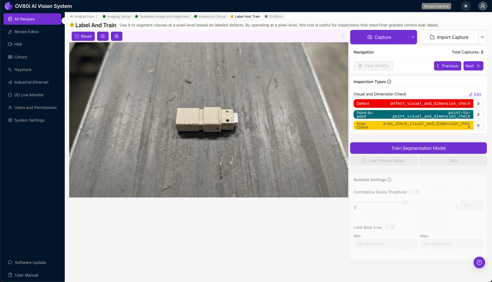
Step 4: Labeling Data
This human-in-the-loop process trains the AI to distinguish acceptable connectors from defective ones. Review captured production images and label each as "Good" (pins present and correctly seated) or "Bad" (missing, broken, or misaligned pins).
Include representative samples across lighting variations, connector lots, and known failure modes. The more diverse your labeled dataset, the more robust your trained model will perform in real-world conditions.
Step 5: Creating Rules
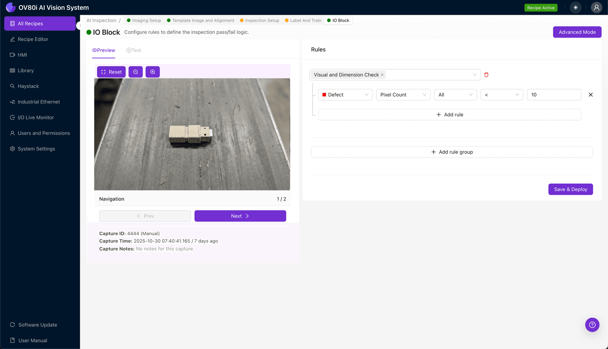
Define your pass/fail logic based on the Inspection Types you created. For MTP connectors, a typical rule requires both "Left Pin Present" AND "Right Pin Present" to return a "Pass" verdict.
These rules gate automated acceptance on the production line. Failed units trigger rejection mechanisms or divert to rework stations—ensuring no defective connectors reach packaging or shipping.
Key Outcomes & ROI
Implementing AI-powered inspection for MTP connector alignment pins delivers measurable business impact:
- Reduced scrap rates — Catch missing pins before connectors proceed to polishing or packaging stages
- Higher throughput — Inspect at line speed without bottlenecking production for manual checks
- Enhanced compliance and traceability — Automatically log inspection images and results for customer audits and quality certifications
- Process improvement insights — Identify upstream assembly issues causing pin defects through trend analysis and defect pattern recognition
Conclusion
Missing alignment pins in MTP connectors represent a high-stakes quality escape that traditional inspection methods struggle to catch consistently. By deploying Overview.ai's visual inspection platform, manufacturers can achieve 100% inline detection, protect their reputation, and transform quality data into actionable process improvements.
Eliminate Alignment Pin Escapes Today
Stop relying on manual inspection for your MTP connector line. Deploy Overview.ai to catch missing pins instantly at full production speed.