
Multi-Fiber Cable with Crossed Polarity Mapping: A Complete Visual Inspection Walkthrough
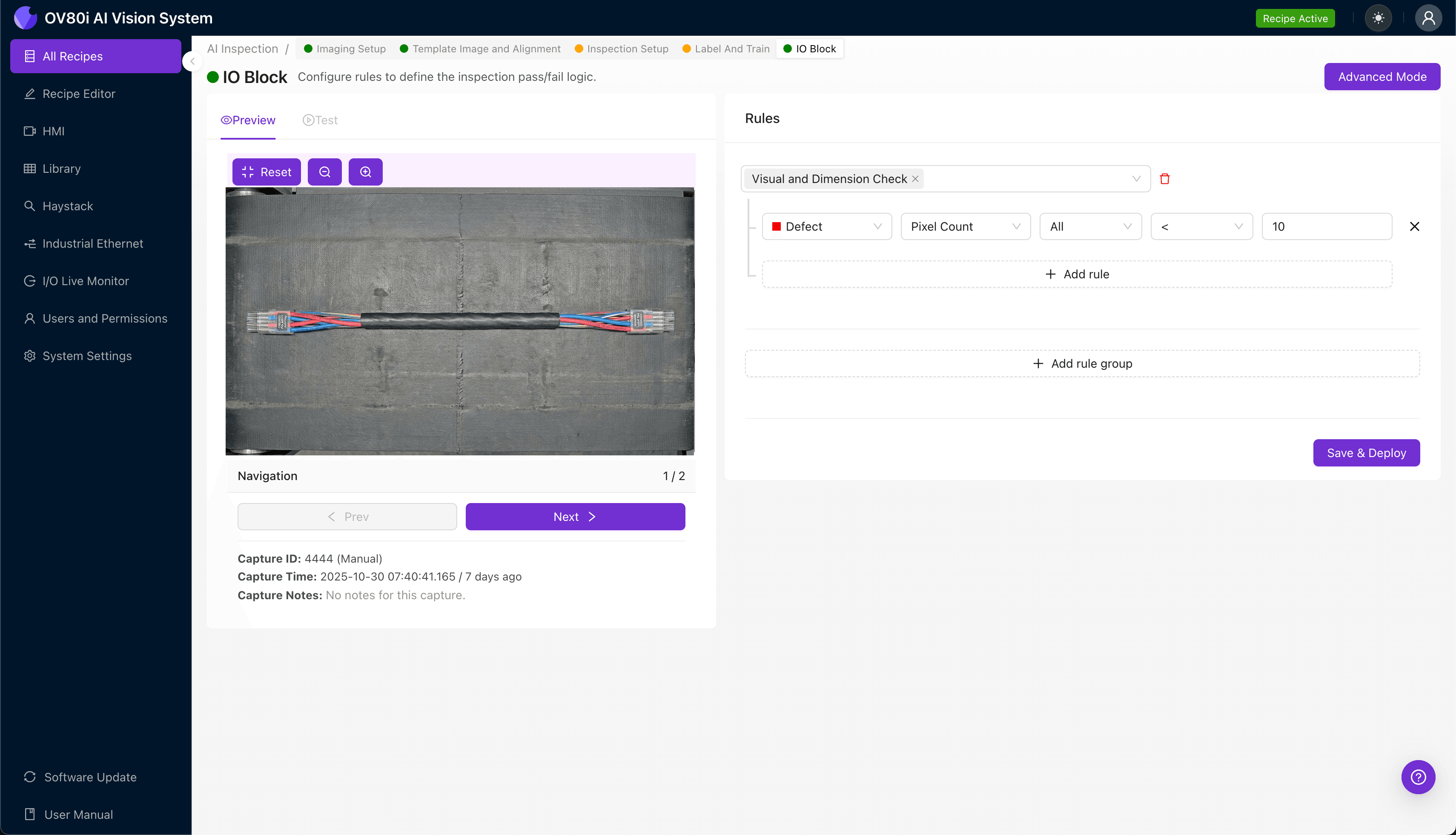
"Multi-fiber cable assemblies with crossed polarity configurations demand inspection precision that human vision cannot deliver at production scale. Overview.ai's machine vision platform verifies fiber position mapping, end face quality, and connector keying at full line speed—eliminating polarity escapes before they reach your customers."
The Problem: Why Polarity Errors Slip Through Manual Inspection
Multi-fiber cable assemblies with crossed polarity configurations are critical components in high-density data center and telecommunications infrastructure. A single polarity mapping error can render an entire cable assembly non-functional—or worse, cause intermittent failures that are nearly impossible to diagnose in the field.
Common Defects in Multi-Fiber Crossed Polarity Cables
- Incorrect fiber position mapping – Fibers routed to wrong connector positions, breaking the A-to-B or A-to-A polarity scheme
- Reversed fiber pairs – Transmit and receive fibers swapped within a pair, causing link failures
- Missing or misaligned ferrule fibers – Fibers not seated properly in the MT ferrule array
- Cross-contaminated end faces – Debris or damage on fiber tips affecting signal transmission
- Incorrect connector keying orientation – Key-up vs. key-down misalignment disrupting polarity method compliance
- Boot and strain relief defects – Improper termination affecting long-term cable reliability
Human inspectors face an impossible task when verifying these assemblies. The sheer density of 12, 24, or even 72 fibers per connector—combined with color-coded mapping schemes that must be traced end-to-end—creates severe cognitive load and eye strain. Manual inspection throughput cannot keep pace with production demands, and inspector fatigue leads to escape rates that increase dramatically across shift hours.
The Solution: Machine Vision + Deep Learning for Polarity Verification
Machine vision systems eliminate the variability inherent in human inspection by capturing high-resolution images of every fiber position and analyzing them against trained models. Deep learning algorithms can learn the complex mapping patterns of Method A, B, and C polarity schemes—detecting deviations that would take a human inspector minutes to verify in mere milliseconds.
Overview.ai's approach delivers consistent, objective inspection at full line speed. The OV80i system inspects 100% of cable assemblies inline, catching polarity errors and termination defects before they ship to customers—protecting both quality metrics and brand reputation.
Step 1: Imaging Setup
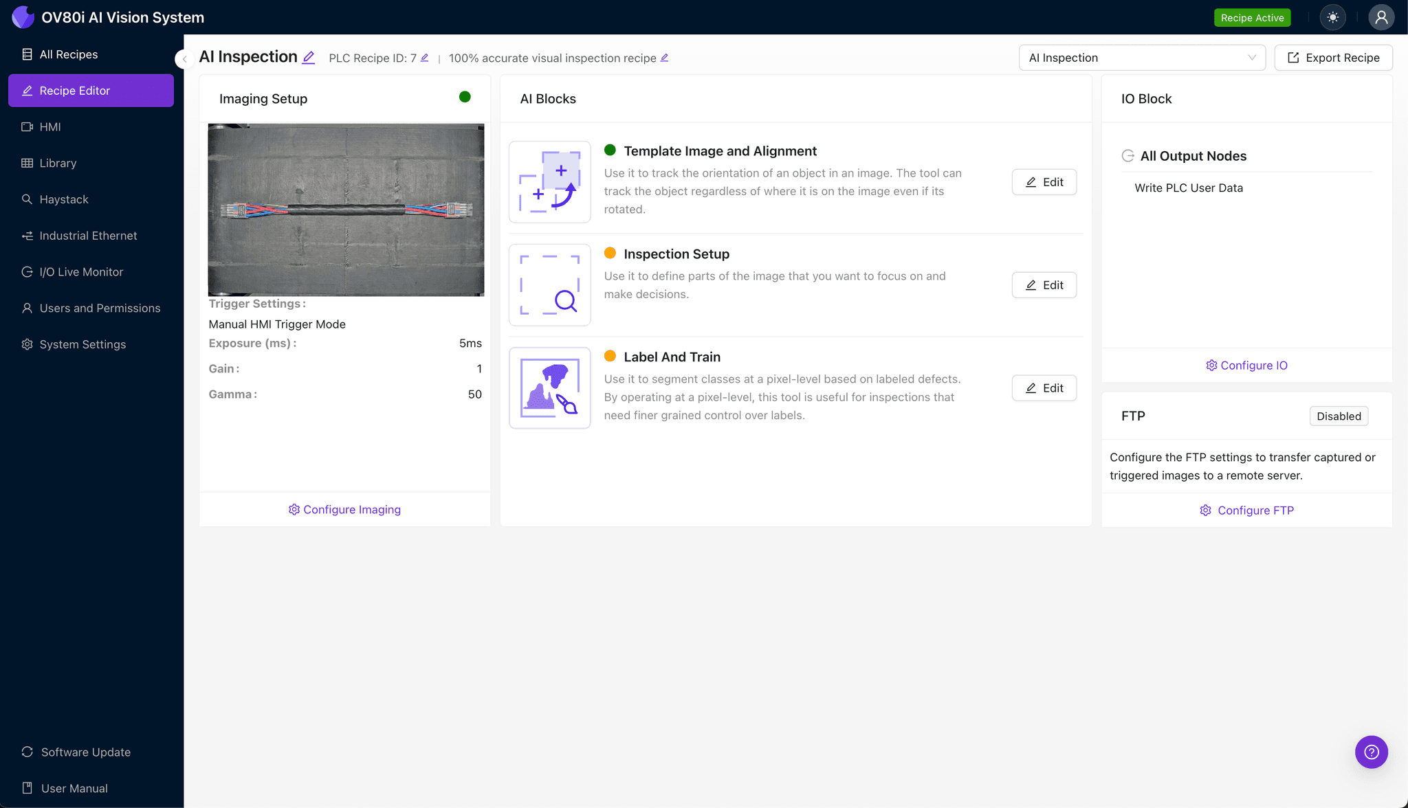
Position the multi-fiber cable connector under the OV80i camera system, ensuring the MT ferrule face or connector end is perpendicular to the lens axis. Proper fixturing is essential—use a connector holder that presents the fiber array at a consistent focal distance.
Click "Configure Imaging" in the Overview.ai interface to access Camera Settings. Adjust exposure to clearly illuminate each fiber position without washout, and fine-tune gain to maximize contrast between fiber cores and the ferrule guide holes.
Click "Save" to lock in your imaging parameters.
Step 2: Image Alignment
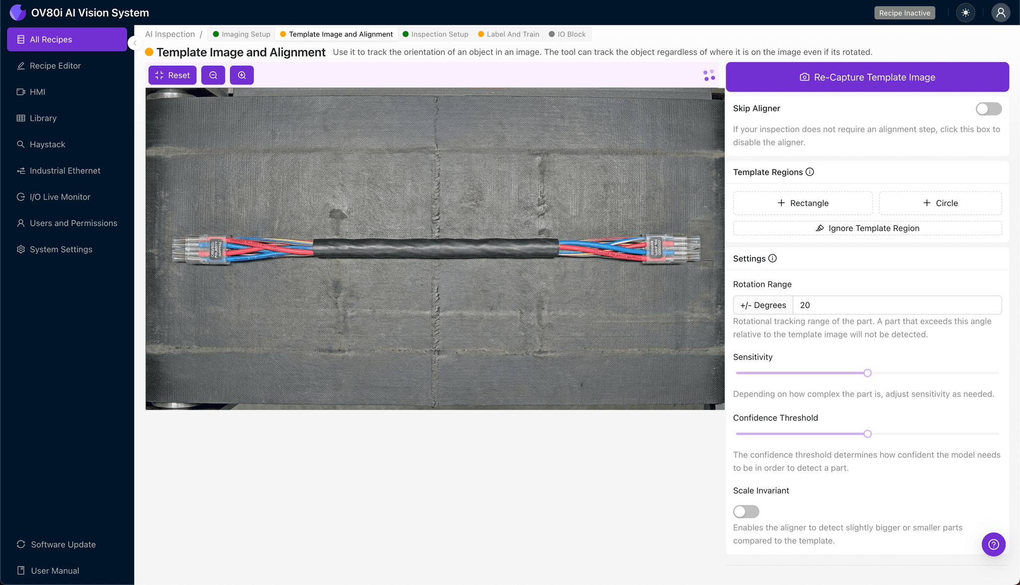
Navigate to the "Template Image" tab and capture a reference image of a known-good cable connector. This template serves as the baseline for all subsequent inspections.
Click "+ Rectangle" to add an alignment region around the main connector body or ferrule housing. This tells the system where to anchor its inspection frame.
Set the "Rotation Range" to 20 degrees to accommodate slight variations in how cables are presented to the camera during production handling.
Step 3: Inspection Region Selection
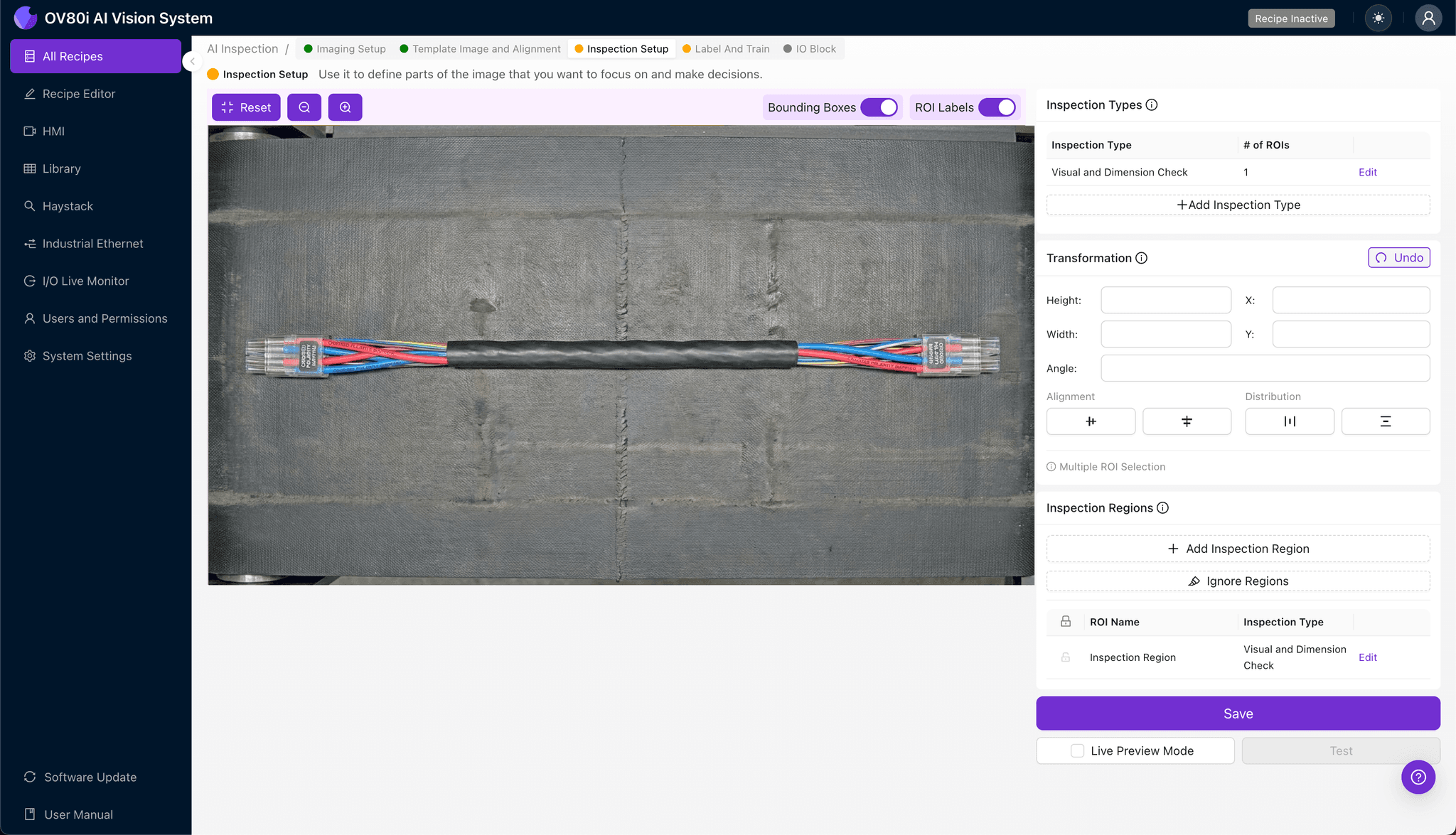
Navigate to "Inspection Setup" from the main menu. Rename your "Inspection Types" to reflect the specific checks required—for example, "Fiber Position Mapping," "End Face Quality," and "Connector Keying."
Click "+ Add Inspection Region" to define your first zone. Resize the yellow bounding box to cover the critical defect area—start with the fiber array itself, ensuring all 12 or 24 fiber positions fall within the region.
Add additional inspection regions for the connector key, boot termination, and any color-coding verification points. Click "Save" after configuring each region.
Step 4: Labeling Data
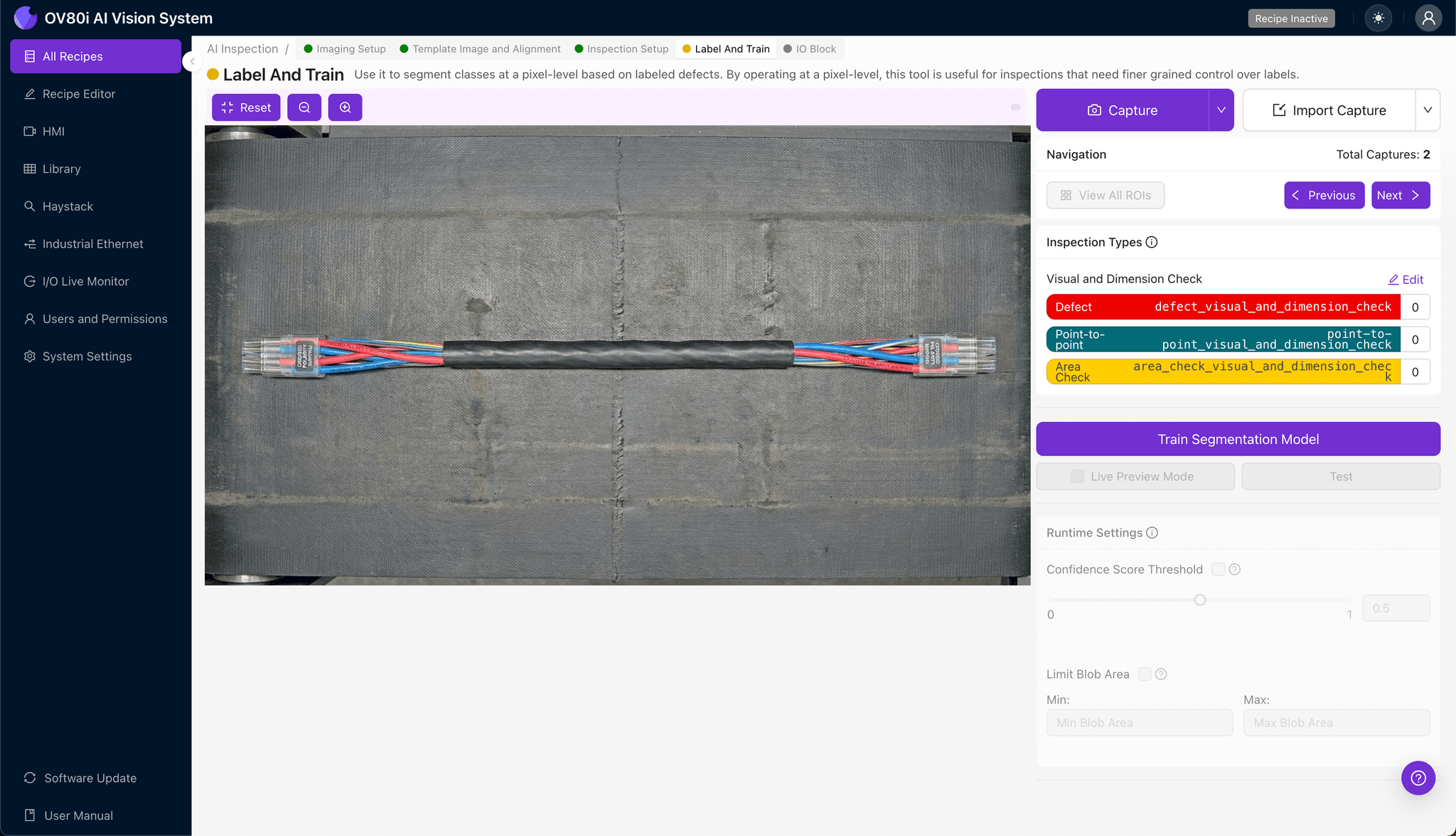
Overview.ai uses a human-in-the-loop approach to train inspection models specific to your product. The system presents captured production images for your quality team to classify.
Label each image as Good or Bad, providing clear examples of acceptable cables and known failure modes. Include representative samples of every defect type: reversed fibers, contaminated end faces, and keying errors.
The more diverse your labeled dataset, the more robust your trained model becomes. Aim for at least 50-100 labeled examples of each defect category before initial deployment.
Step 5: Creating Rules
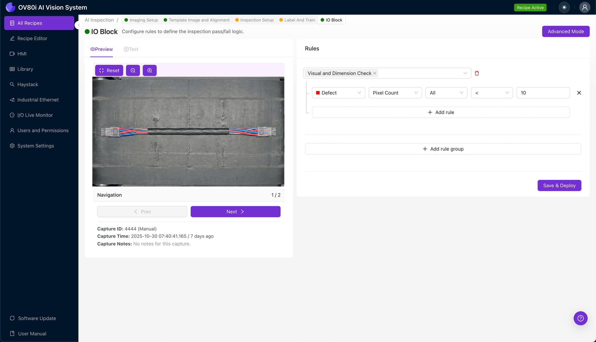
Navigate to the Rules configuration panel to set your pass/fail logic. Define acceptance criteria based on your Inspection Types—for example, "Fail if Fiber Position Mapping confidence is below 95%" or "Fail if any End Face Quality region detects contamination."
These rules gate automated acceptance on the production line. Cables that pass all inspection criteria proceed to packaging, while flagged units are automatically diverted for rework or secondary review.
Key Outcomes & ROI
Deploying automated visual inspection for multi-fiber polarity verification delivers measurable business impact:
- Reduced scrap and rework costs – Catch polarity errors before final assembly, preventing write-offs on completed cable assemblies
- Higher throughput – Inspect every unit at line speed without creating inspection bottlenecks or requiring additional headcount
- Compliance and traceability – Automatically log inspection images and results for every cable, supporting ISO 9001 and customer audit requirements
- Process improvement insights – Identify trending defect patterns to address upstream issues in fiber routing, termination, or connector sourcing
Ready to Eliminate Polarity Escapes?
Multi-fiber cable assemblies with crossed polarity mapping demand inspection precision that human vision simply cannot deliver at production scale. See how the OV80i detects the defects that matter most to your customers.