Machine vision lighting: techniques, geometry, and how to choose
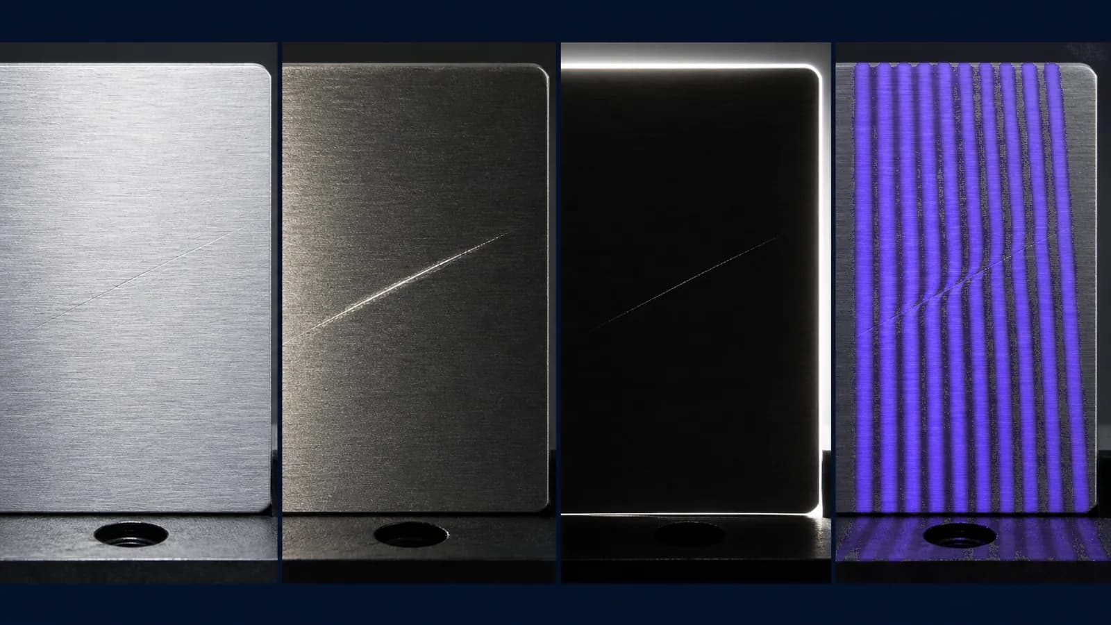
Most inspection projects that fail do not fail on the algorithm. They fail because the defect was never properly visible in the image, and no model can find what the camera did not capture. Lighting is the step that decides that, and it happens before a single line of software runs.
This is a practical guide to machine vision lighting: the geometries available, how to choose one starting from the defect rather than from a catalogue, and the mistakes that quietly cost accuracy for years.
Why lighting decides the outcome
A camera records contrast. A defect is detectable when it produces a difference in brightness against the surface around it, and invisible when it does not. Lighting is the only tool that controls that difference, which is why it outranks resolution, lens choice, and model architecture in the order of things that matter.
The clearest way to see this is the same part photographed two ways.
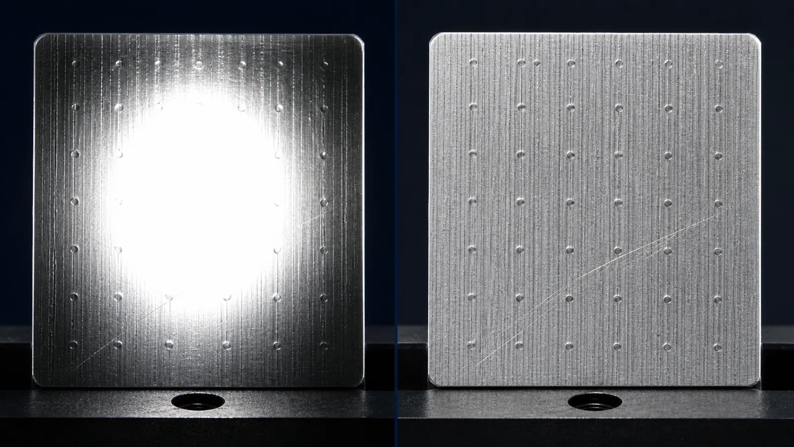
Nothing about the software changed between those two frames. If a project is struggling with false rejects or missed defects, lighting is the first place to look, not the last.
The six geometries worth knowing
Lighting choices are usually described by where the light comes from relative to the part and the camera. Six arrangements cover almost all industrial inspection.
Diffuse dome
Light arrives from many angles at once, which suppresses shadows and specular hotspots. The default for textured, matte, or curved surfaces where you want the material to read evenly. Weak at revealing shallow topography.
Ring or coaxial
Light travels along the camera axis, so flat specular surfaces return it straight back and read bright while anything tilted reads dark. Strong on polished metal and for finding dents and engraving on flat parts.
Dark field
Light strikes the part at a shallow angle, so a smooth surface stays dark and only edges, scratches, and raised particles scatter light into the lens. The best tool for fine surface defects and for reading text on a difficult finish.
Backlight
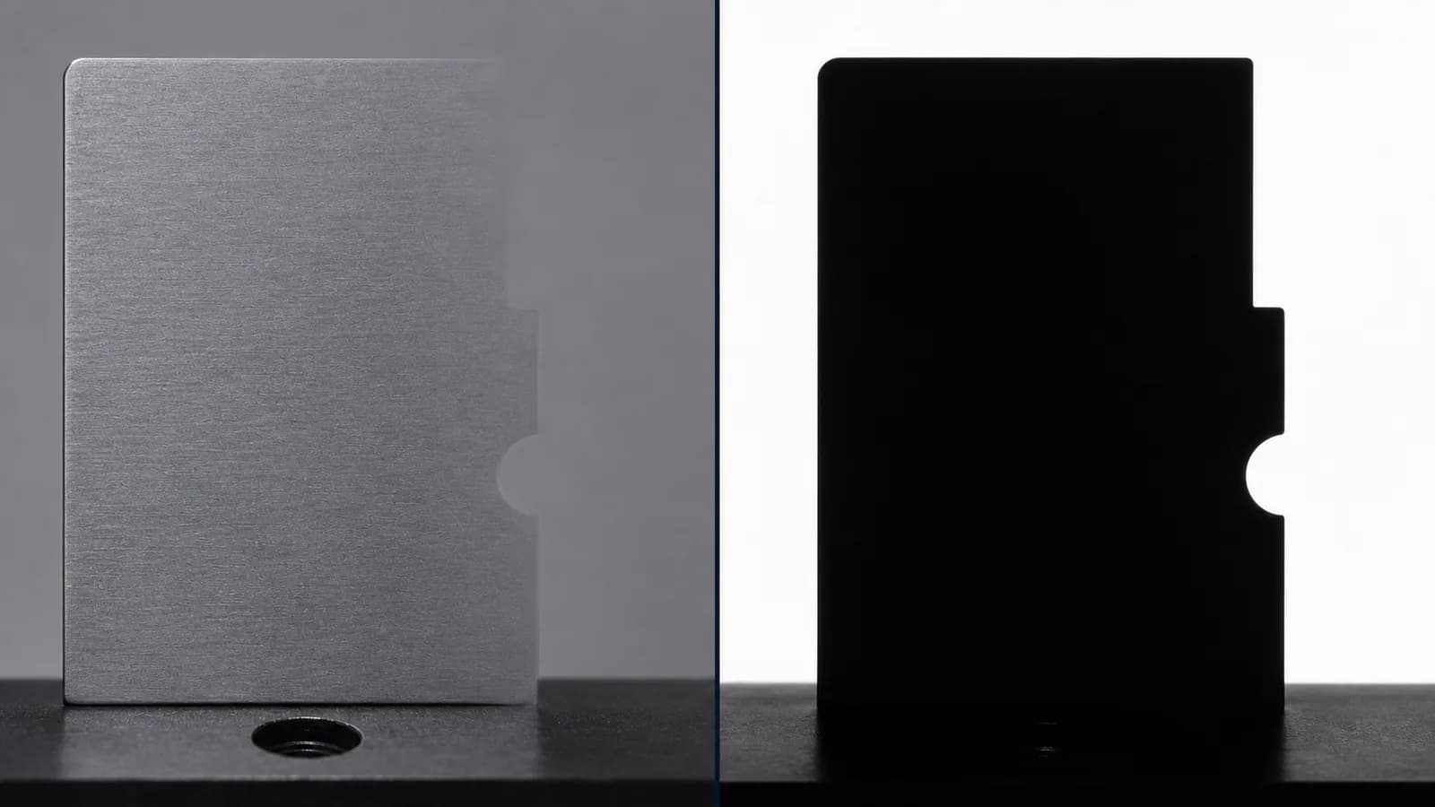
Light sits behind the part and the camera sees a silhouette. Unbeatable for dimensional measurement, presence and absence, and hole or gap checks, because the edge it produces is high contrast and repeatable.
Directional or bar
A light from one side casts controlled shadows that make embossing, engraving, and surface relief measurable. Useful when the feature is a height difference rather than a colour difference.
Multi-angle, sometimes called 2.5D
Several illumination directions captured in sequence and combined, so the system infers surface slope rather than just brightness. This is what makes reflective and specular parts practical rather than a fight.
Backlighting deserves a special mention because it is the one geometry that turns a measurement problem into an easy one.
Choose the light from the defect, not the catalogue
The useful question is not which light is best. It is what physical property distinguishes a bad part from a good one, because that property dictates the geometry.
| What separates good from bad | Start with |
|---|---|
| A shape, a size, or a gap | Backlight |
| A fine scratch or scuff on a smooth surface | Dark field |
| A dent, a coin mark, or engraving on flat metal | Coaxial or ring |
| A stain, a colour shift, or contamination | Diffuse dome |
| Raised or recessed relief you need to quantify | Directional bar |
| Anything on a shiny, curved, or specular part | Multi-angle |
A worked example. A fine tool mark on a polished surface is a topography difference, not a colour difference, so diffuse light will wash it out no matter how bright you make it. Dark field, which leaves the smooth surface dark and lights only what scatters, is the geometry that makes it appear.
Five mistakes that cost accuracy quietly
1. Relying on ambient factory light
Overhead lighting changes with the time of day, the season, a nearby door opening, and someone standing in the wrong place. Every one of those variations reaches the model as a change in the part. Shield the station and control its own light.
2. Turning brightness up instead of changing geometry
If the defect is invisible, more of the same light usually makes it worse by saturating the surface. Brightness is not the variable. The angle is.
3. Leaving the lighting adjustable after commissioning
Adjustability is essential while you are finding the setup and a liability afterwards. Once it works, lock it mechanically. A model trained under one illumination and run under another is being asked a different question.
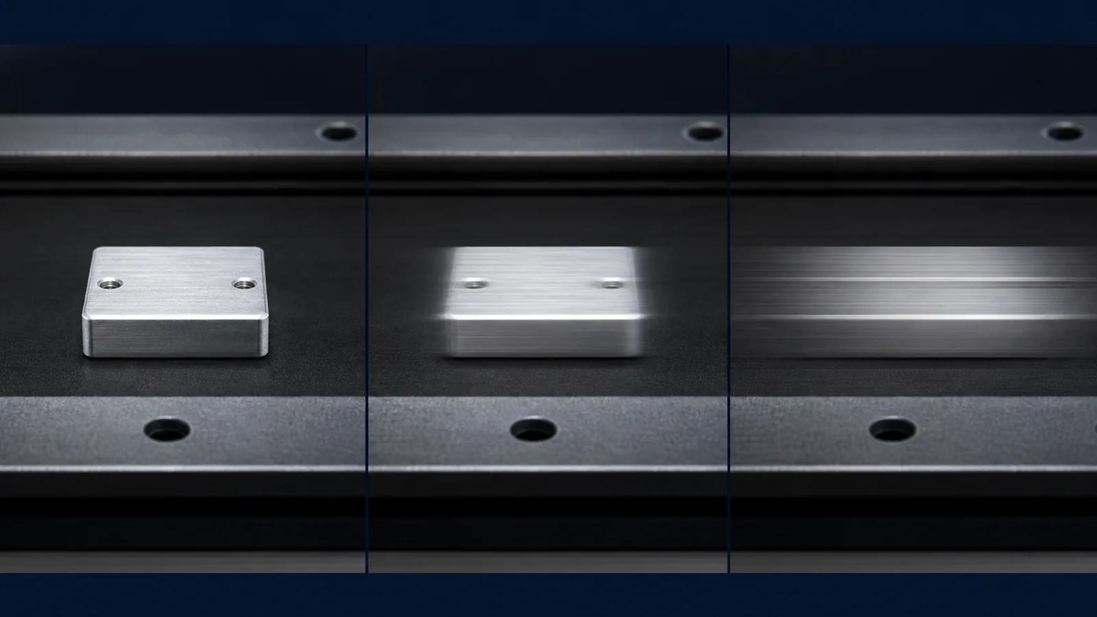
4. Ignoring exposure and motion together
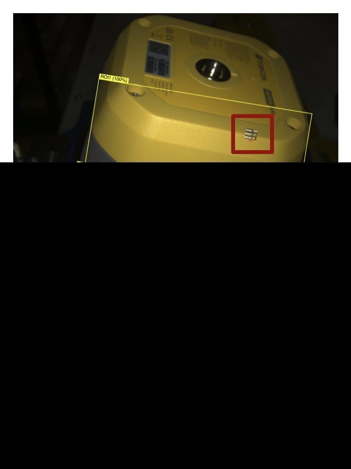
Lighting and exposure are one decision. A short exposure freezes a moving part but needs more light, and the intensity you can deliver caps the line speed you can inspect. Work them together, not in sequence.
5. Testing on clean samples only
A setup validated on pristine parts meets reality at the first oily, dusty, or slightly misaligned one. Include the marginal parts your team argues about, because those are the ones the lighting has to resolve.
That fourth point is worth expanding, because exposure time is where lighting meets line speed.
How this changes with AI inspection
A learned model is more tolerant than a rule-based tool. Rule-based logic measures a threshold, so a shift in illumination moves the measurement and breaks the rule. A model trained across the normal range of variation absorbs some of that, which is one reason AI inspection copes with surfaces that classical setups struggle on.
Tolerance is not a substitute for control, though. Every bit of variation the model has to absorb is capacity spent on lighting instead of on the defect, and it shows up as more training images needed for the same accuracy. Good lighting reduces the amount of learning you have to buy.
The practical consequence is that integrated lighting is worth more than it looks. Every Overview camera ships with illumination in the same housing, aligned to the sensor and fixed by construction, so the geometry cannot drift and there is no separate light to specify, mount, wire, or lose. Where a surface genuinely needs multi-angle capture, the OV20i handles it photometrically rather than requiring a lighting rig.
A short commissioning sequence
- Name the physical property that separates a good part from a bad one. Shape, topography, colour, or relief.
- Pick the geometry that maximises that property from the table above, and try the obvious alternative alongside it.
- Capture the same parts under both, including your marginal parts, and compare the images rather than debating the theory.
- Set exposure against your line speed, then confirm you still have the light for it.
- Fix everything mechanically, then collect training images through the setup you are actually going to run.
Once lighting is settled, the rest of the optics follows arithmetic rather than judgement. Our optics calculators turn a part size and a defect size into a field of view, a working distance, and a lens, and the industrial camera guide covers the sensor decisions that sit alongside it. For the wider picture of how these pieces form a station, see our guide to machine vision systems.
Frequently Asked Questions
What type of lighting works best for machine vision inspection?
There is no single best lighting, only the geometry that matches your defect. Diffuse dome lighting suits stains and colour variation on matte or curved surfaces. Dark field lighting is the strongest choice for fine scratches, because a smooth surface stays dark and only the defect scatters light into the lens. Coaxial or ring lighting suits dents and engraving on flat specular metal. Backlighting is the right answer for dimensional measurement and presence checks. Testing two candidate geometries on your own parts is faster and more reliable than reasoning about it.
How does lighting affect AI model accuracy?
Lighting controls the contrast between the defect and the surface around it, and a model can only learn from contrast that exists in the image. Poor or inconsistent illumination spends model capacity on compensating for the image rather than on the defect, which raises both false rejects and missed defects and increases the number of training images needed to reach a given accuracy. Consistency matters more than absolute brightness.
Should machine vision lighting be fixed or adjustable?
Adjustable while you are commissioning, fixed once it works. Variable lighting introduces drift that degrades a model over time, because it was trained under one illumination and is being run under another. Identify the configuration during setup, then lock it mechanically and shield the station from ambient light.
How do I light a reflective or shiny part?
Avoid single diffuse or single direct sources, both of which produce specular hotspots that hide defects. Multi-angle capture, sometimes called 2.5D, illuminates from several directions in sequence and combines the frames so the system reads surface slope rather than raw brightness. Coaxial lighting also works on flat specular parts, because a flat surface returns light along the camera axis and any tilted feature reads dark against it.
Can I use existing factory lighting for machine vision inspection?
Generally no. Overhead and area lighting varies with time of day, nearby activity, and anyone standing in the wrong place, and every one of those variations reaches the model as an apparent change in the part. A shielded station with its own controlled illumination produces more consistent results and needs less training data to reach the same accuracy.
Does lighting limit how fast a line can be inspected?
Yes, indirectly. Freezing a moving part requires a short exposure, a short exposure requires more light, and the intensity you can deliver therefore caps the speed you can inspect without motion blur. Lighting and exposure should be specified together against the line speed rather than one after the other.
See how Overview AI inspects vision system lighting
Send us a photo of your part or defect and a vision engineer will tell you whether Overview can catch it, with most systems deployed on the line in days.
Related Articles
Industrial Camera Selection for AI Inspection
How to choose the camera hardware that sits behind the lighting, and the specs that actually decide the outcome.
Read More →Telecentric Lenses in Machine Vision
What a telecentric lens fixes, when it is the only correct answer, and when it is an expensive habit.
Read More →Global Shutter vs Rolling Shutter
Why a rolling shutter skews a moving part, and how to tell which one your inspection needs.
Read More →