Case Study: Detecting minute bent pins and dust particles with two images and a telecentric lens
A global electronics manufacturer needed to automate inspections of multi-pin header connectors for bent pins and dust. Manual inspection was slow and led to a 2% miss rate. We built a segmenter recipe on the OV80i, pairing it with a telecentric lens to eliminate perspective distortion. With 2 training images (1 only good pins, 1 only bad pins) and customized logic in “Node-Red” (no code tool) to calculate pin position, we achieved 100% accuracy in ~3h. The ability to pair AI with custom optics, and logic made for a unique solution.
- Industry: Electronics
- Application: Bent pins
- Key Challenge: Extremely high accuracy to detect bent pins
- Time to Train: <1h setup/training
- Accuracy: 100% accuracy
Accuracy across test samples (n=25)
Time to set-up & train segmenter algorithm
Images to setup & train segmenter recipe
Getting to this performance level & accuracy was impressive. The team had good lens knowledge & getting multiple classes of defects with logic was impressive
See next section for detailed report
Problem:
Manual inspection of the header connectors was slow, costly, and unreliable, leading to a consistent 2% miss rate for subtle pin bends. This was hard due to:
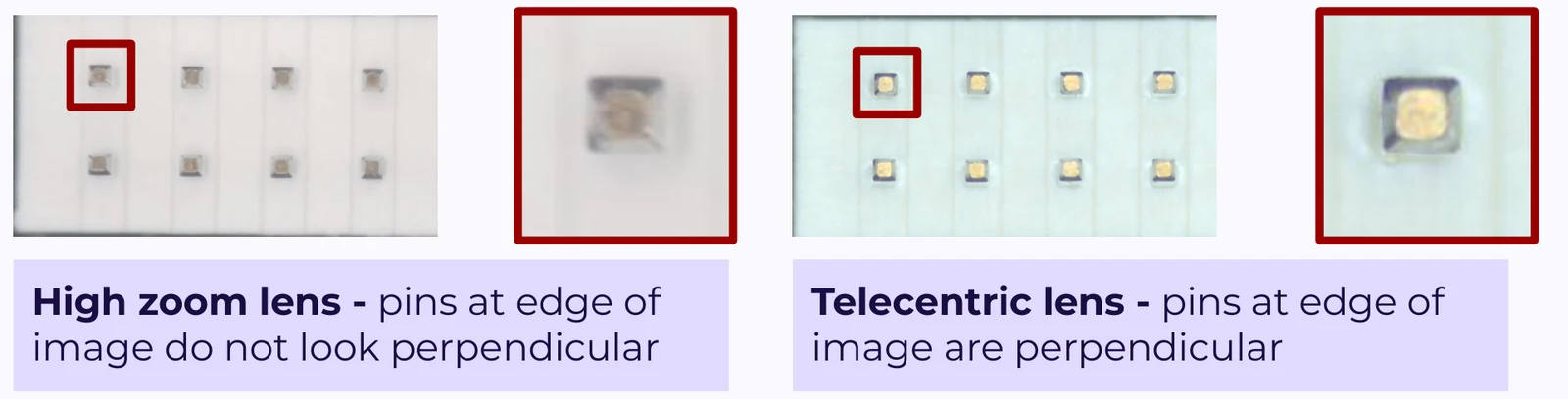
- Perspective Distortion: With a standard lens, pins on the connector edge appear to be at a different angle than the center causing overkill.
- 3D Variation: Pins can be bent slightly in any direction (X, Y, or Z axis), which is challenging for 2D rule-based systems to handle reliably.
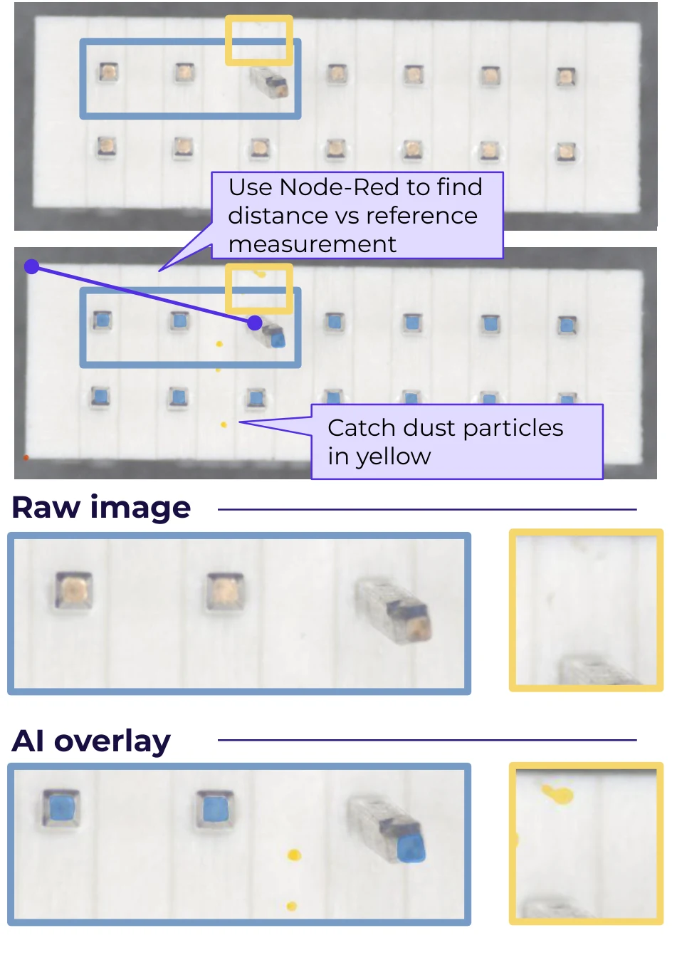
- Multiple defects: In addition to bent pins, dust particles could settle on connectors. These were individually, manually cleaned prior to packing.
Solution:
We implemented a classifier algorithm on the OV80i using a telecentric lens with 0.3x magnification to reduce perspective error. This setup ultimately allowed us to reliably capture all 7 defect types in 1 system.
Setup:
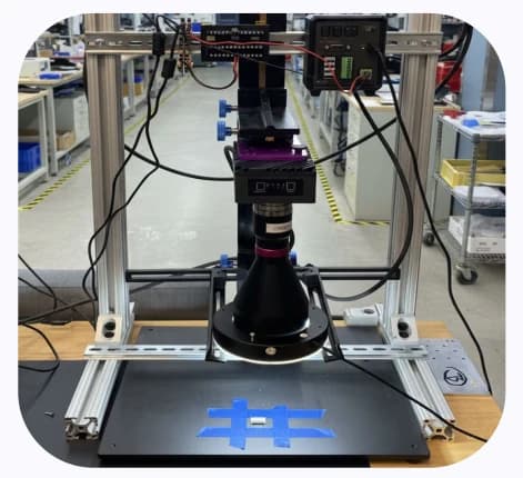
Step 1: Hardware setup
- Camera: OV80i at a working distance of 110 mm
- Lens: 0.3x magnification telecentric lens
- Light: Standard ring light
Step 2: Alignment and inspection setup
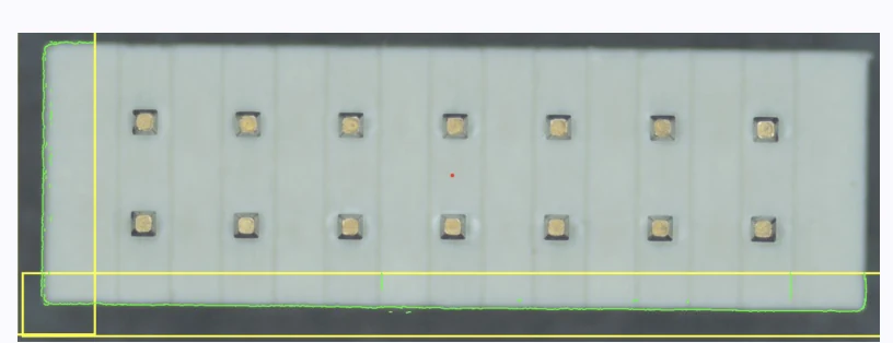
Set up alignment so each component can be reliably inspected, independent of how they are placed by machinery. Left and bottom edges are used for alignment
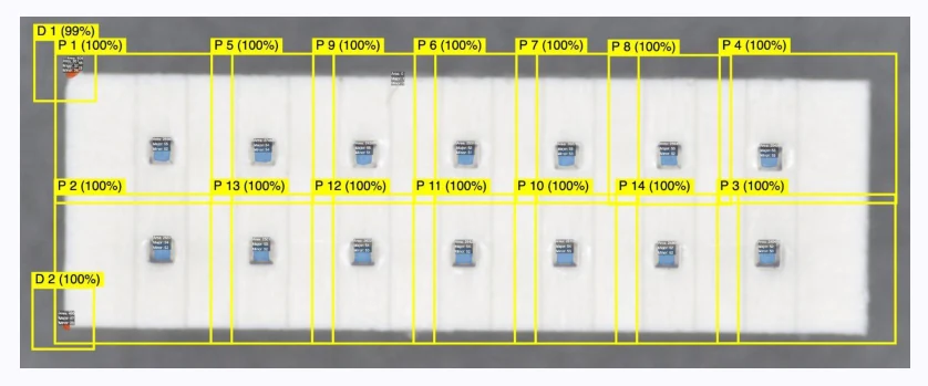
Create two types of inspections:
- ROI covering top and bottom corners for reference measurements
- ROI covering pin tops
Step 4: Training Classification
We trained on 2 samples - 1 good connector where all pins were correct, 1 bad connector where all pins were bent. Total of 28 ROIs (14 pins on each)
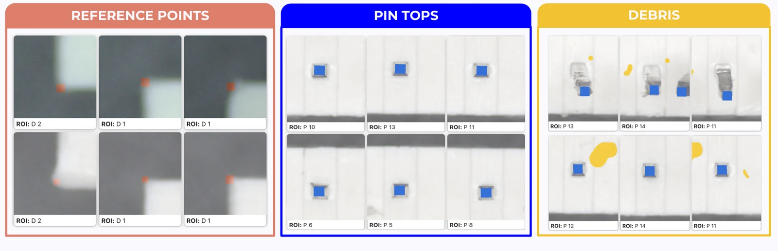
Step 5: Testing
Tested on 15 good samples and 10 defective samples, achieving 100% accuracy with zero misses and zero overkills. Examples of a pass, fail due to a bent pin, and fail due to debris and a bent pin are shown below

Result: Pass
Reason: All pins within 10 pixels (~0.1 mm); no debris
Result: Fail
Reason: Pin 5 failure in vertical direction by ~45 pixels (~0.45 mm); no debris
Result: Fail
Reason: Pin 3 horizontal & vertical failure; multiple dust particles
- Pass / fail for measurement was identified using “Node-Red”. Sample example flow with custom functions to calculate pin distances and create a dashboard are shown below
- +/- 5 pixel tolerance was allowed (~50 µm)
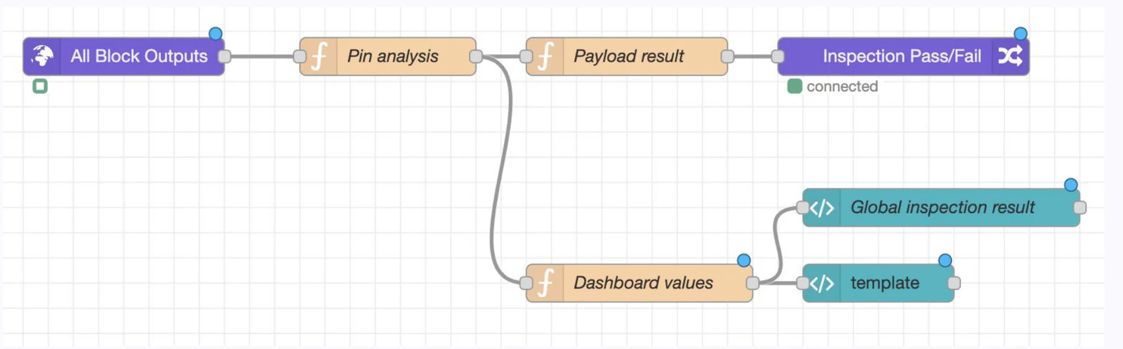
- Reference values for top row of pins:
- ◦ X-dist: 159 +/- 5
- ◦ Y-dist: 108 +/-5
| Datum | Pin 1 | Pin 2 | Pin 3 | Pin 4 | Pin 5 | Pin 6 | |
|---|---|---|---|---|---|---|---|
| X-center | 22 | 182 | 182 | 181 | 181 | 215 | 180 |
| Y-center | 426 | 318 | 315 | 318 | 320 | 402 | 319 |
| X-dist | - | 160 | 160 | 159 | 159 | 193 | 158 |
| Y-dist | - | 108 | 111 | 108 | 106 | 24 | 107 |
| X-pass | - | pass | pass | pass | pass | fail | pass |
| Y-pass | - | pass | pass | pass | pass | fail | pass |
| Overall | - | PASS | PASS | PASS | PASS | FAIL | PASS |
Take the next step toward zero defects and higher efficiency.
Contact Overview at contact@overview.ai or +1 (844) 799-7044
Timings are reproduced as published. The document quotes both "<1h setup/training" in the specification list and ~3 hours to set up and train the segmenter. Ask us for the exact breakdown if you are planning against it.