How to Inspect Alignment Frames with Oversized Tolerance (Slop) Using AI-Powered Visual Inspection
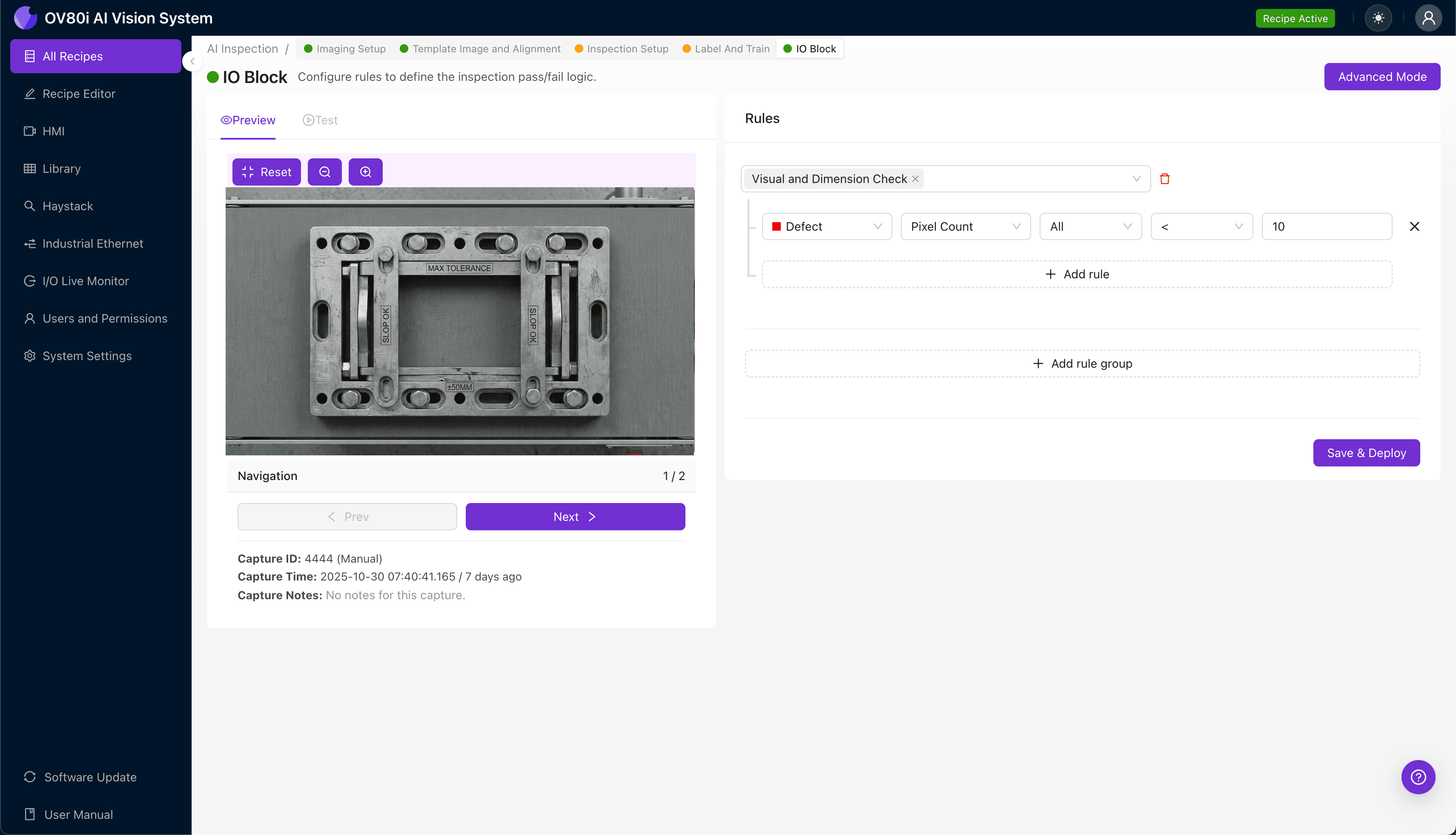
"Oversized tolerance in alignment frames causes assembly failures and costly warranty claims. AI-powered visual inspection catches subtle dimensional anomalies—like 0.05mm variations—that human inspectors consistently miss, delivering objective quality control at full line speed."
The Problem: Why Loose-Fitting Alignment Frames Slip Past Manual Inspection
Alignment frames are critical structural components that position and secure assemblies in automotive, aerospace, and industrial manufacturing. When these frames exhibit oversized tolerance—commonly called "slop"—the resulting play or looseness can cascade into catastrophic assembly failures, premature wear, and costly warranty claims.
Common Defects in Alignment Frames with Oversized Tolerance
- Excessive bore diameter — Mounting holes machined beyond specification limits
- Worn locating pin holes — Enlarged openings from tooling degradation or improper feeds/speeds
- Uneven slot width — Asymmetrical material removal causing inconsistent fit
- Out-of-round conditions — Ovality in critical circular features meant for press-fit connections
- Surface galling or deformation — Metal displacement from repeated assembly attempts masking true dimensional issues
- Burr accumulation at edges — Excess material altering effective clearance measurements
Human inspectors struggle to detect these subtle tolerance deviations consistently. Visual fatigue sets in quickly when evaluating frame after frame, and the human eye cannot reliably distinguish 0.05mm variations across thousands of parts per shift.
The Solution: Machine Vision and Deep Learning for Tolerance Inspection
Traditional go/no-go gauges catch only the most extreme oversized conditions, missing borderline parts that degrade over time. AI-powered visual inspection systems leverage deep learning algorithms trained on thousands of images to detect subtle dimensional anomalies invisible to manual methods.
Overview.ai's approach delivers consistent, objective inspection at full line speed—eliminating the subjectivity and fatigue that plague human quality control. The system learns what "good" looks like and flags any deviation, regardless of shift changes or production pressure.
Step 1: Imaging Setup
Position the alignment frame under the OV80i camera, ensuring the critical tolerance zones (bore holes, locating features, slots) are clearly visible. The frame should be oriented consistently with how it travels down your production line.
Click "Configure Imaging" in the Overview interface. Adjust Camera Settings—increase exposure to reveal machined surface details, and fine-tune gain to capture edge definition without overexposure.
Click "Save" to lock in your optimized settings.
Step 2: Image Alignment
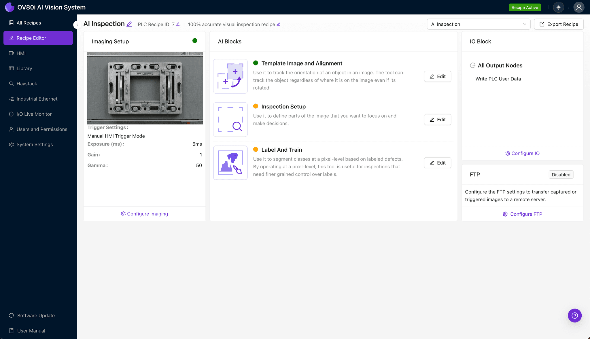
Navigate to the "Template Image" section and capture a reference image of a known-good alignment frame. This template anchors the system's understanding of correct part positioning.
Click "+ Rectangle" to add a region around the frame's main body and primary mounting features. Set the "Rotation Range" to 20 degrees to accommodate natural variation in part presentation on the conveyor.
Step 3: Inspection Region Selection
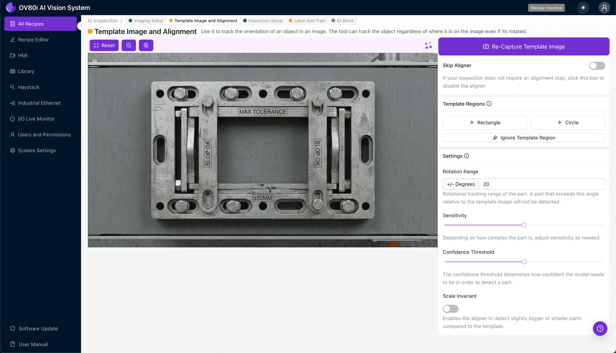
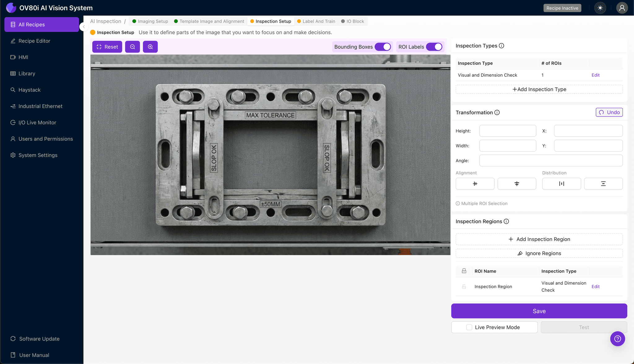
Navigate to "Inspection Setup" and rename your "Inspection Types" to match specific tolerance zones—for example, "Primary Bore Tolerance," "Locating Pin Fit," or "Slot Width."
Click "+ Add Inspection Region" for each critical area. Resize the yellow bounding box to cover the specific features where slop manifests—bore circumferences, pin hole edges, and slot sidewalls.
Click "Save" after defining all regions.
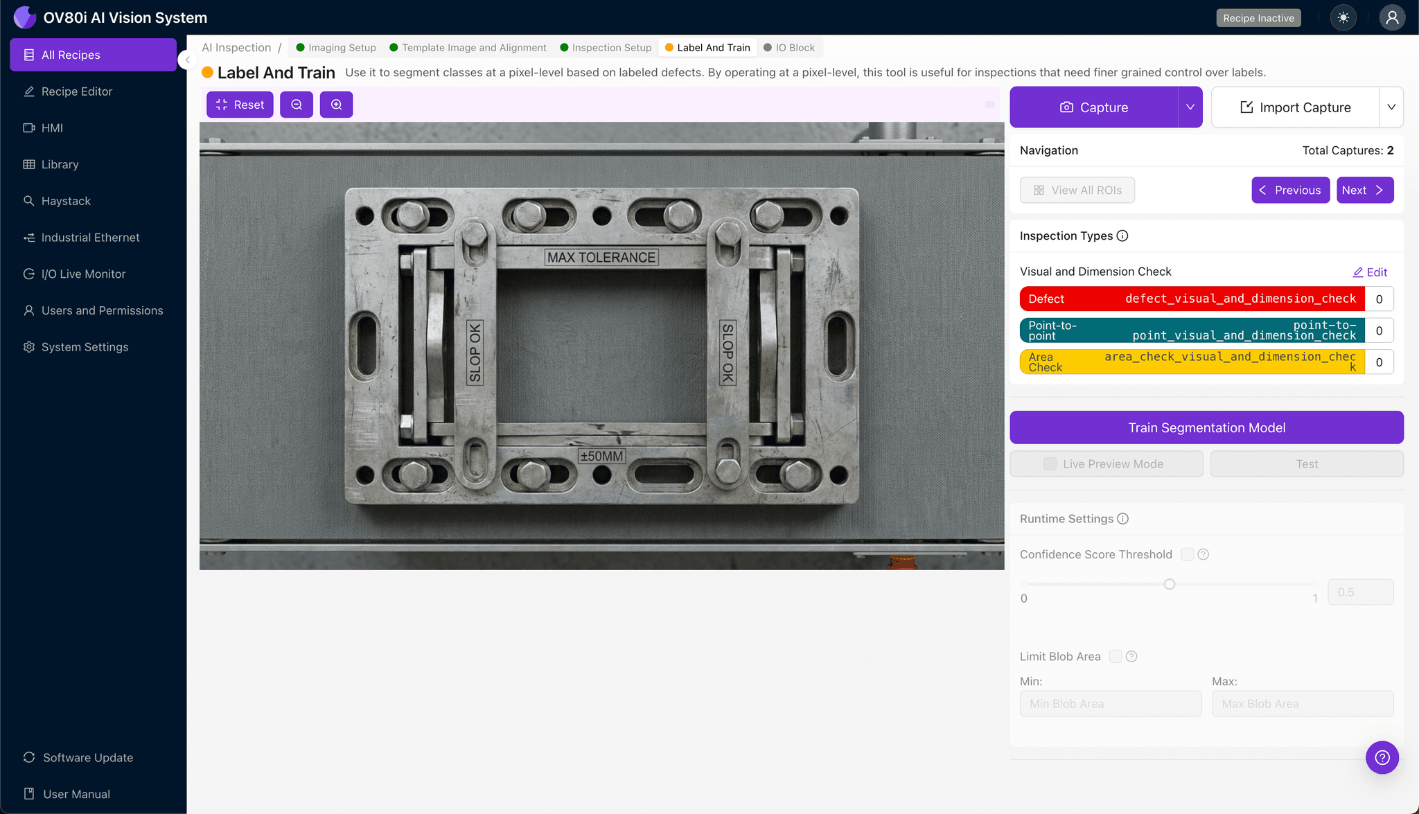
Step 4: Labeling Data
This human-in-the-loop process builds the AI's understanding of acceptable versus rejectable conditions. Quality engineers review captured images and label them as Good (within tolerance) or Bad (oversized/excessive slop).
Include representative samples across the full spectrum: ideal parts, borderline acceptable parts, and known failure modes like worn tooling output or material defects. The more diverse your labeled dataset, the more robust your inspection model becomes.
Step 5: Creating Rules
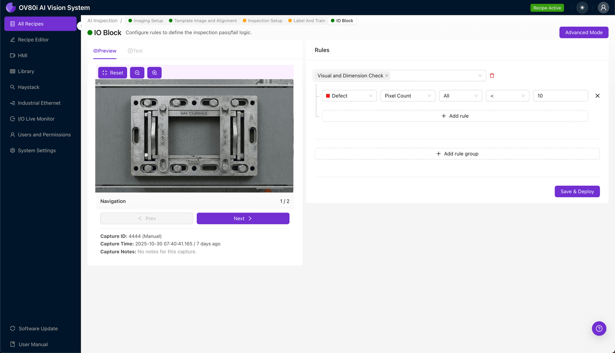
Set your pass/fail logic based on Inspection Type results. For example: "If Primary Bore Tolerance = Bad OR Locating Pin Fit = Bad, then REJECT."
These rules gate automated acceptance on the line, ensuring only conforming alignment frames proceed to downstream assembly.
Key Outcomes & ROI
Deploying AI-powered inspection for alignment frame tolerance delivers measurable business impact:
- Reduced scrap and rework costs — Catch oversized parts before they enter assembly, eliminating downstream teardowns
- Higher throughput — Inspect 100% of parts at line speed without creating inspection bottlenecks
- Enhanced compliance and traceability — Automatically log every inspection with timestamped images for audit trails and customer quality documentation
- Process improvement insights — Identify tooling wear trends and machining drift before they cause batch-wide tolerance excursions
Stop Shipping Sloppy Frames
Oversized tolerance in alignment frames isn't just a quality issue—it's a liability waiting to happen. Overview.ai's visual inspection platform catches what human eyes miss, protects your production line, and builds the data foundation for continuous improvement.
Eliminate Tolerance Defects Today
Stop relying on manual inspection and go/no-go gauges. Deploy Overview.ai to catch oversized tolerance instantly.