High-Speed D-Sub with Bent Coax Inserts: A Complete Visual Inspection Guide
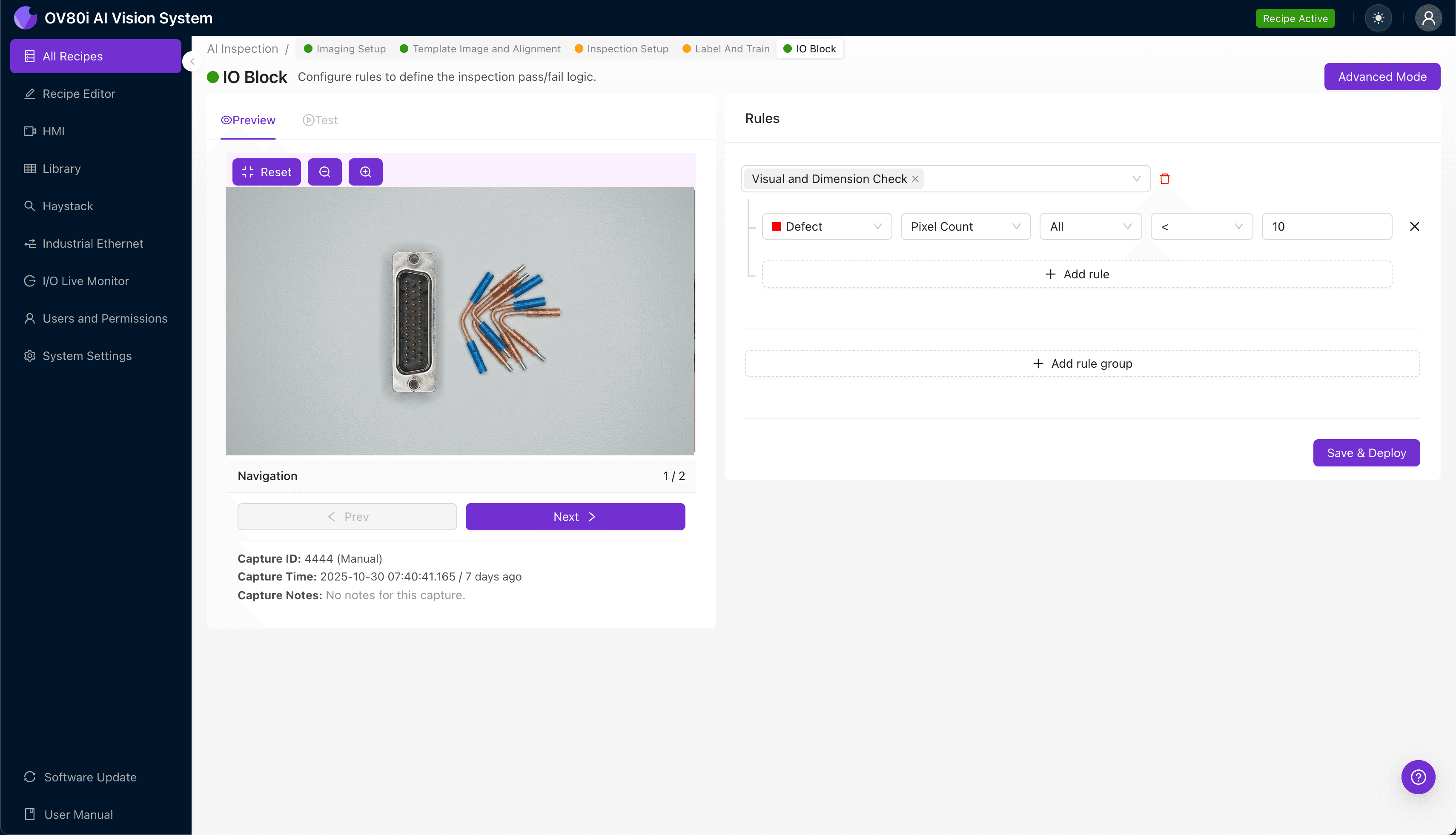
"High-speed D-sub connectors with bent coax inserts demand microscopic precision that human inspectors cannot sustain. AI-powered visual inspection delivers 100% repeatability, catching bent contacts, improper seating, and damaged insulators at full line speed."
The Problem: Why Manual Inspection Falls Short
High-speed D-sub connectors with bent coax inserts are critical components in aerospace, defense, and telecommunications applications where signal integrity cannot be compromised. Even minor defects can cause catastrophic system failures in the field.
Common Defects in High-Speed D-Sub with Bent Coax Inserts:
- Bent or misaligned coax contacts — contacts deflected beyond acceptable tolerance during insertion
- Improper seating depth — coax inserts not fully seated in the connector housing
- Damaged center conductors — bent, broken, or recessed center pins within the coax cavity
- Cracked or chipped insulators — dielectric material damage compromising signal performance
- Missing or rotated inserts — empty cavities or incorrectly oriented coax elements
- Housing damage — scratched plating, bent shells, or damaged mounting hardware
Human inspectors struggle with these components due to the sheer number of contact points requiring verification. Inspector fatigue sets in quickly when examining dozens of microscopic features under magnification, leading to inconsistent pass/fail decisions and escaped defects.
The Solution: AI-Powered Visual Inspection
Machine vision systems equipped with deep learning algorithms eliminate the variability inherent in manual inspection. These systems never tire, never lose focus, and apply identical inspection criteria to every single part.
Overview.ai's approach delivers consistent, objective inspection at full line speed. The OV80i system learns to identify defects the way an expert inspector would—but with 100% repeatability and complete traceability for every component inspected.
Step 1: Imaging Setup
Position the high-speed D-sub connector under the camera with the coax insert face oriented toward the lens. Ensure consistent lighting eliminates shadows within the deep coax cavities.
Click "Configure Imaging" to access the Camera Settings panel. Adjust exposure to capture detail in both the reflective metal contacts and darker insulator areas, then fine-tune gain to optimize contrast.
Click "Save" to lock in your imaging configuration.
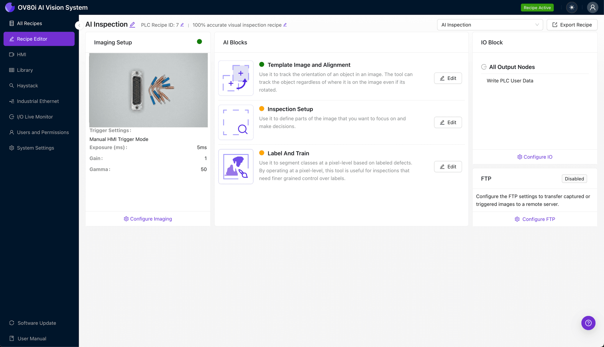
Step 2: Image Alignment
Navigate to "Template Image" in the setup menu. Capture a Template using a known-good connector positioned in the standard orientation.
Click "+ Rectangle" and draw a region around the main connector body, encompassing all coax insert locations. Set the "Rotation Range" to 20 degrees to accommodate natural variation in part presentation on the line.
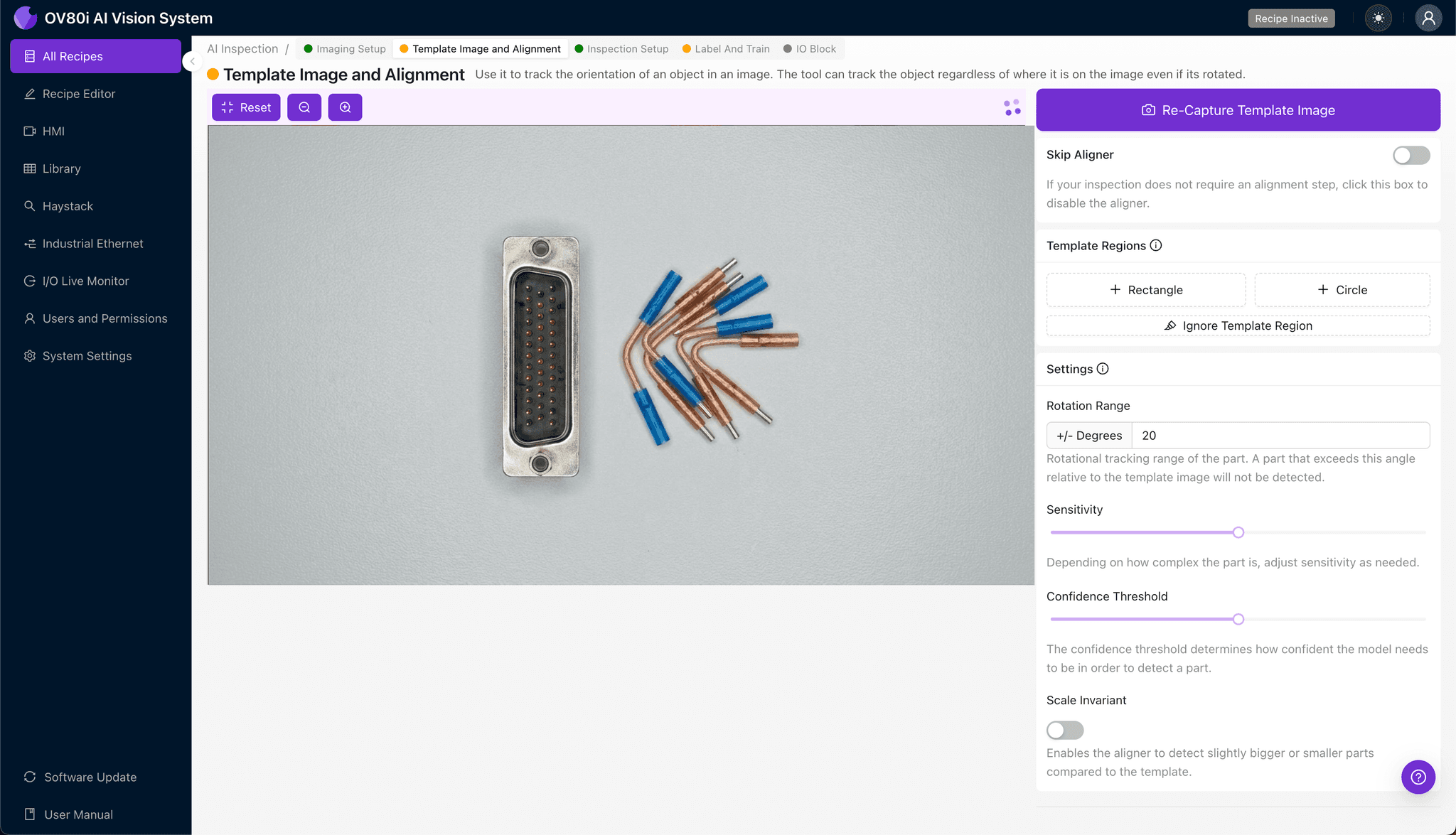
Step 3: Inspection Region Selection
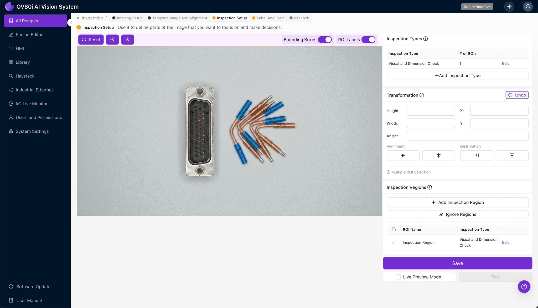
Navigate to "Inspection Setup" to define your critical inspection zones. Rename your "Inspection Types" to match specific defect categories—for example, "Coax_Seating," "Center_Conductor," and "Insulator_Damage."
Click "+ Add Inspection Region" for each coax insert location. Resize the yellow bounding box precisely over each coax cavity where defects are most likely to occur.
Click "Save" after defining all inspection regions.
Step 4: Labeling Data
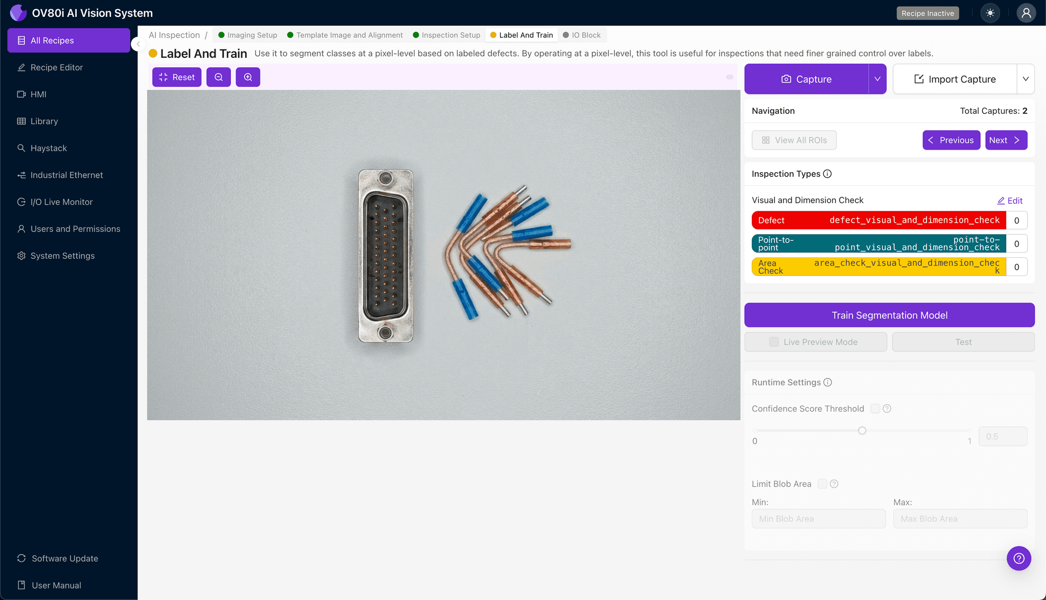
The human-in-the-loop labeling process teaches the AI what constitutes acceptable versus rejectable parts. Review captured images and label each as Good or Bad based on your quality standards.
Include representative samples across the full range of acceptable variation. Importantly, incorporate known failure modes—even rare defect types—to ensure the model learns to catch edge cases that would otherwise escape detection.
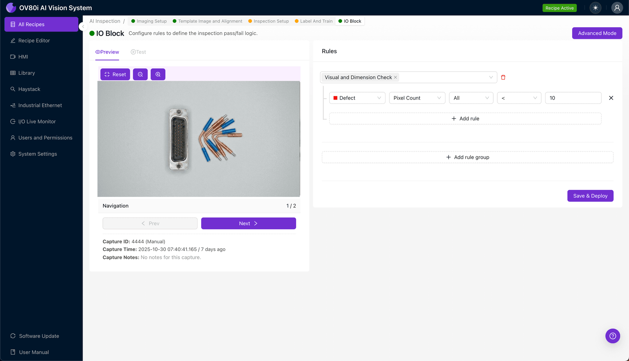
Step 5: Creating Rules
Define your pass/fail logic based on the Inspection Types you created. For example, any "Bad" classification on "Center_Conductor" or "Coax_Seating" triggers an automatic reject.
These rules gate automated acceptance on the production line. Parts meeting all criteria proceed automatically, while flagged components are diverted for secondary review or scrap.
Key Outcomes & ROI
Implementing automated visual inspection for high-speed D-sub connectors delivers measurable business impact:
- Reduced scrap and rework — catch defects before value-added assembly operations
- Higher throughput — inspect at line speed without creating bottlenecks
- Compliance and traceability — maintain complete inspection records for AS9100, MIL-SPEC, and customer audits
- Process improvement insights — identify defect trends to address root causes upstream
Conclusion
High-speed D-sub connectors with bent coax inserts demand inspection precision that manual methods simply cannot sustain. Overview.ai's AI-powered visual inspection ensures every connector meets specification—protecting your customers, your reputation, and your bottom line.
Eliminate Defects Today
Stop relying on manual inspection. Deploy Overview.ai to catch defects instantly.