How to Detect Cracked Bridge Defects in Orthogonal Connectors Using AI Vision Inspection
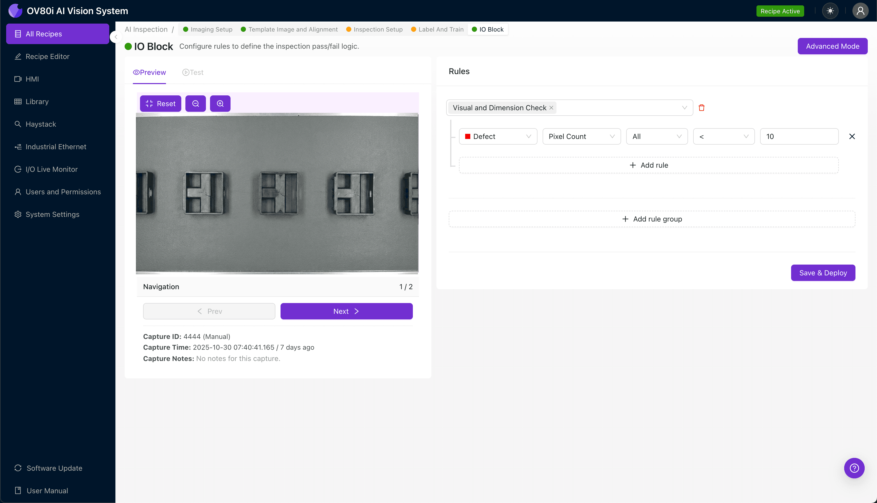
"Cracked bridges in orthogonal connectors are nearly invisible to human inspectors yet cause catastrophic field failures. Deep learning-powered vision inspection catches hairline cracks, incomplete formations, and stress whitening at full production speed—eliminating quality escapes before they reach your customers."
The Problem: Why Cracked Bridges Slip Through Traditional Inspection
Orthogonal connectors are precision components essential for reliable electrical connections in automotive, aerospace, and industrial applications. The bridge feature—the thin structural element connecting contact pins—is particularly vulnerable to cracking during molding, handling, and assembly processes.
Common Defects in Orthogonal Connectors with Bridge Features:
- Hairline bridge cracks — Microscopic fractures that compromise structural integrity but remain invisible to the naked eye
- Incomplete bridge formation — Partial molding defects where the bridge material fails to fully connect
- Stress whitening — Material discoloration indicating internal stress concentrations near crack initiation points
- Edge chipping — Small fragments breaking away from bridge corners during ejection or handling
- Delamination lines — Separation between material layers that precede catastrophic failure
- Surface pitting — Small voids or porosity defects that weaken the bridge cross-section
Manual inspection of these defects is fundamentally unreliable. Human inspectors experience fatigue after just 20-30 minutes of repetitive visual tasks, and their detection consistency drops significantly across shifts. At production speeds of hundreds or thousands of parts per hour, the human eye simply cannot maintain the focus required to catch subtle bridge cracks.
The Solution: Machine Vision Powered by Deep Learning
Traditional rule-based machine vision struggles with bridge crack detection because cracks vary dramatically in appearance—different lighting angles, crack orientations, and material colors create infinite variations that simple threshold algorithms cannot handle.
Deep learning changes the game entirely. By training neural networks on thousands of labeled examples, AI systems learn to recognize the concept of a cracked bridge rather than relying on rigid pixel-matching rules.
Overview.ai's approach delivers consistent, objective inspection at full line speed. The OV80i system examines every single part with the same attention to detail, eliminating the variability inherent in human inspection while keeping pace with your fastest production cycles.
Step 1: Imaging Setup
Position your orthogonal connector sample under the OV80i camera, ensuring the bridge features are clearly visible from above. Proper lighting angle is critical—side lighting often reveals crack shadows more effectively than direct illumination.
Click "Configure Imaging" to access the camera controls. Adjust exposure time to capture detail without washing out reflective plastic surfaces, and fine-tune gain settings to balance brightness with noise reduction.
Click "Save" once your image shows crisp bridge detail with good contrast.
Step 2: Image Alignment
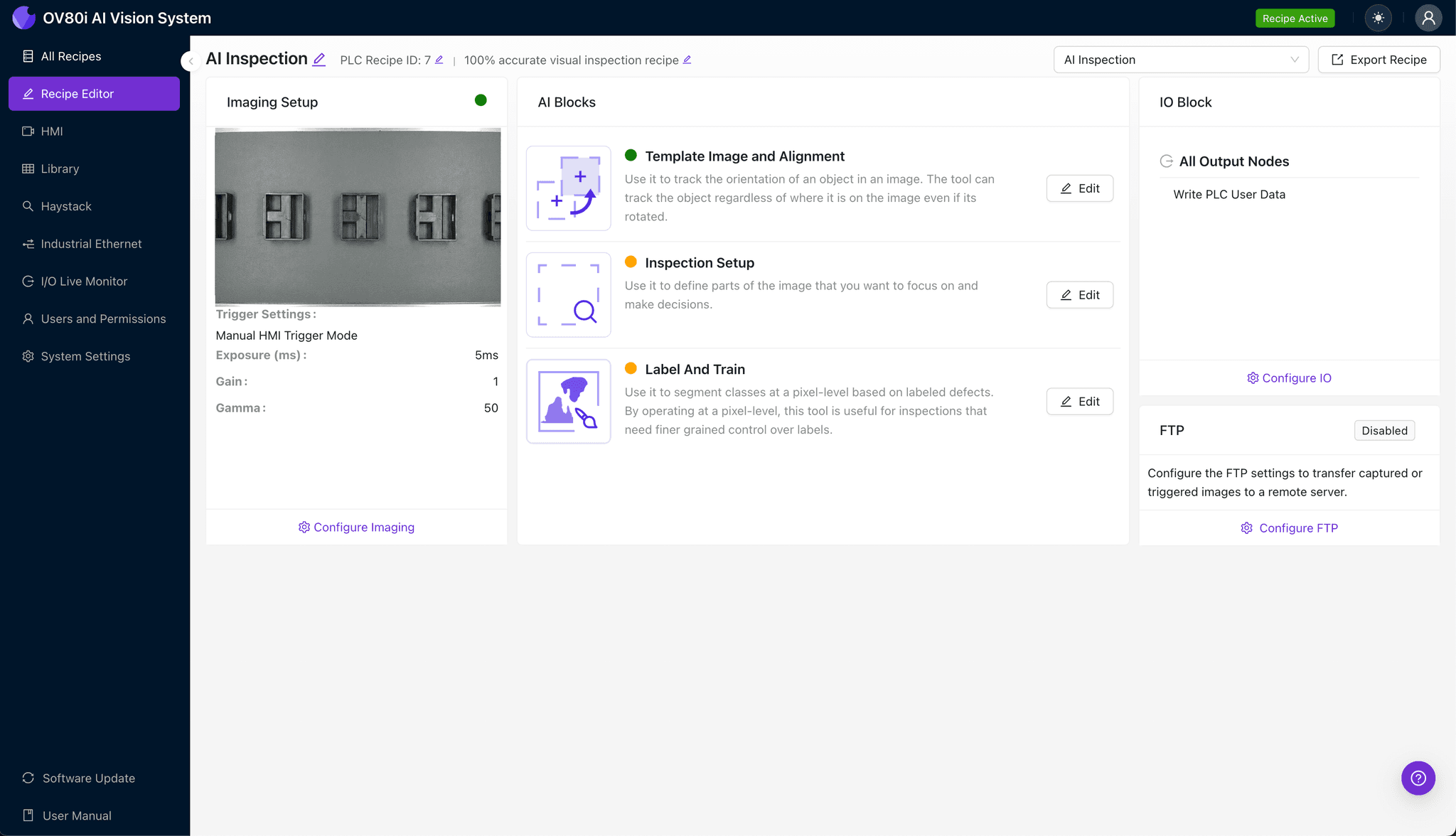
Navigate to the "Template Image" section in the configuration menu. Capture a high-quality template image of a known-good connector in your standard orientation.
Click "+ Rectangle" to add an alignment region around the connector's main body outline. This gives the system stable reference geometry for part location.
Set the "Rotation Range" to 20 degrees to accommodate normal variation in how parts present to the camera on your conveyor or fixture.
Step 3: Inspection Region Selection
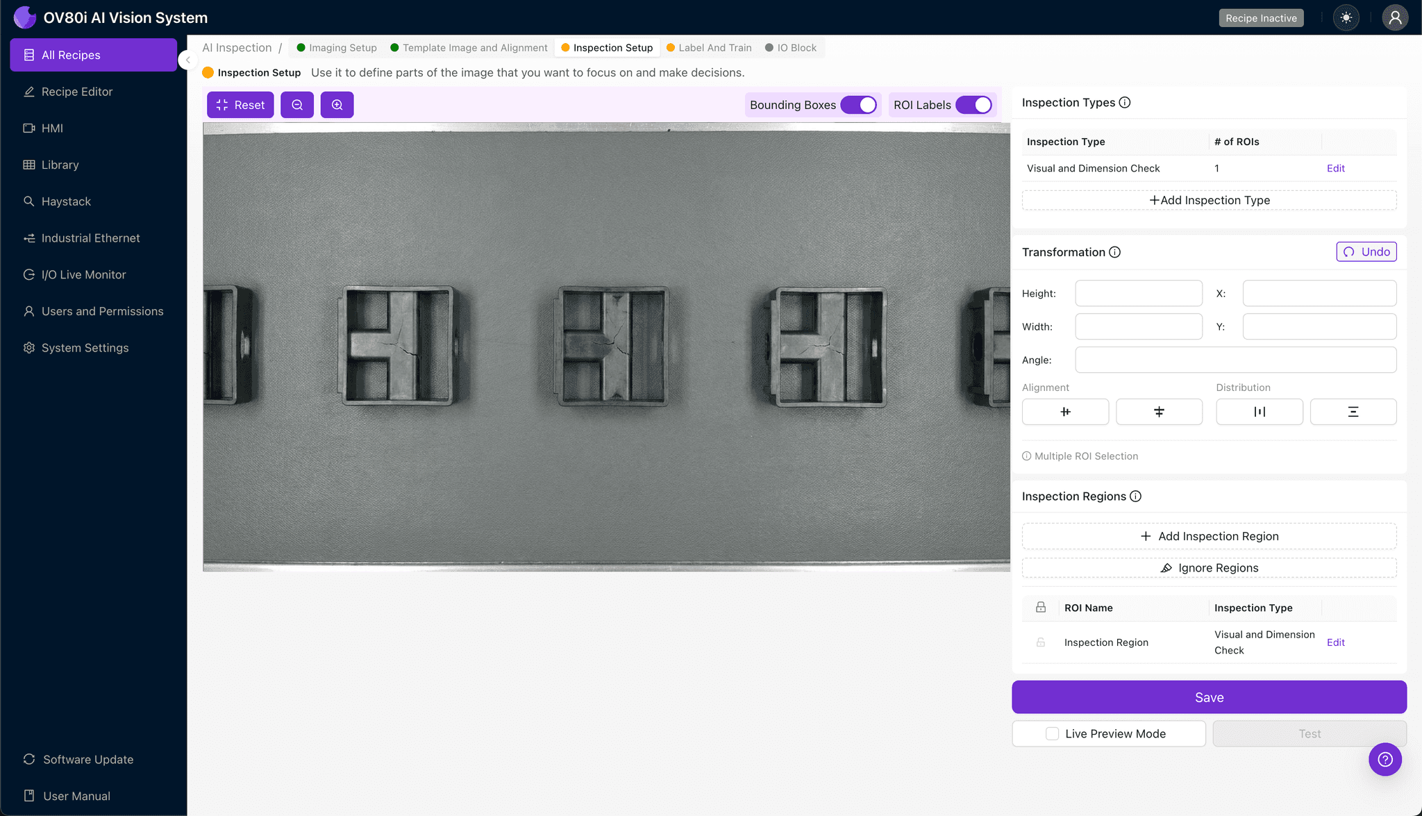
Navigate to "Inspection Setup" to define your critical inspection areas. Rename the default "Inspection Types" to descriptive labels like "Bridge_Crack_Zone_1" and "Bridge_Crack_Zone_2" for clear identification.
Click "+ Add Inspection Region" to create your first zone. Resize the yellow bounding box to cover the bridge feature precisely—include a small margin around the bridge edges where cracks commonly initiate.
Repeat for each bridge location on your connector. Click "Save" to lock in your inspection regions.
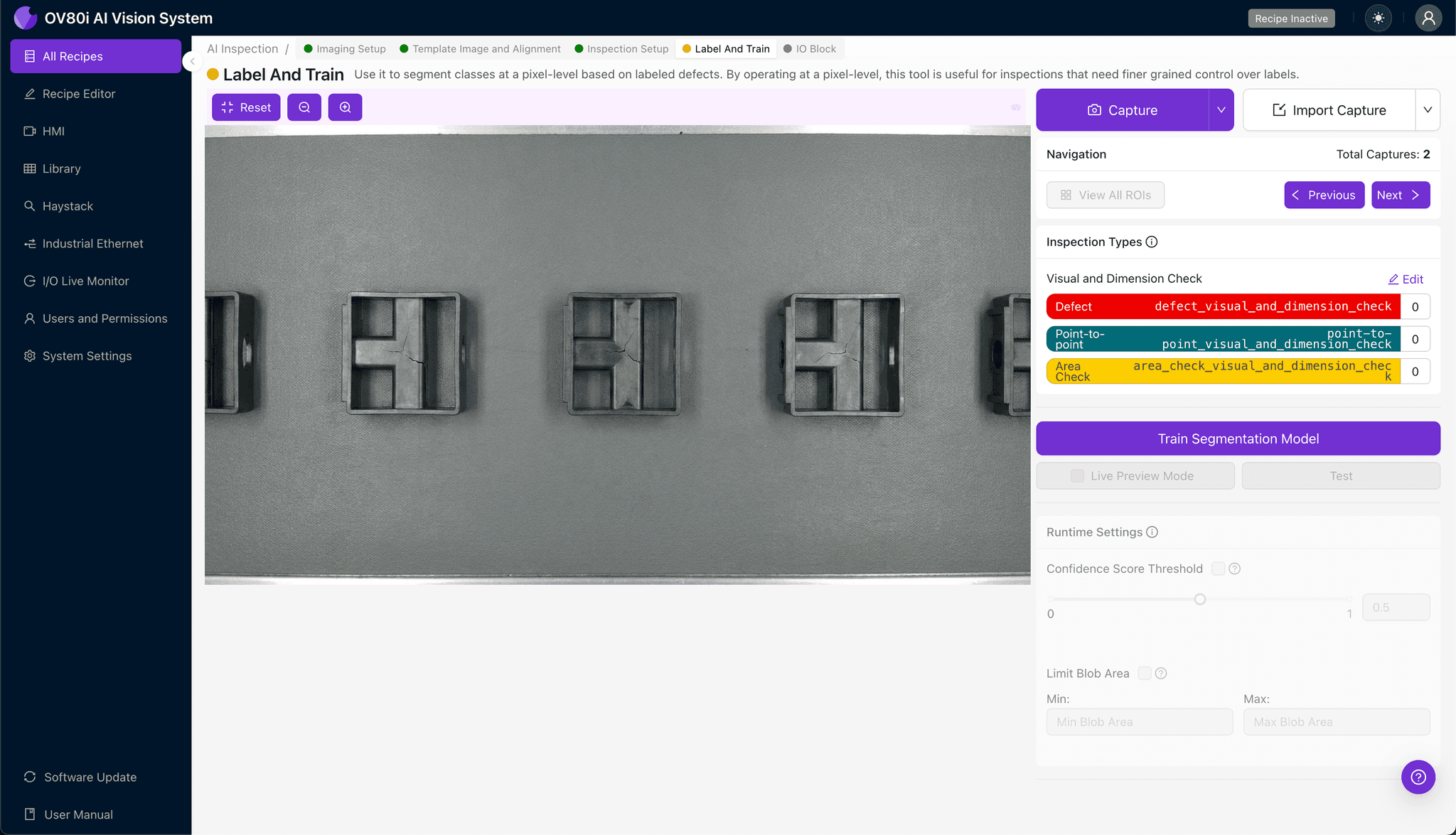
Step 4: Labeling Data
This is where human expertise trains the AI system. The platform presents production images for your team to classify.
Label images as Good (acceptable bridge condition) or Bad (visible cracks, chips, or defects). Include representative samples across your full range of acceptable variation.
Most importantly, include known failure modes from your quality history. The more examples of actual cracked bridges you provide, the more reliably the system will catch them in production.
Step 5: Creating Rules
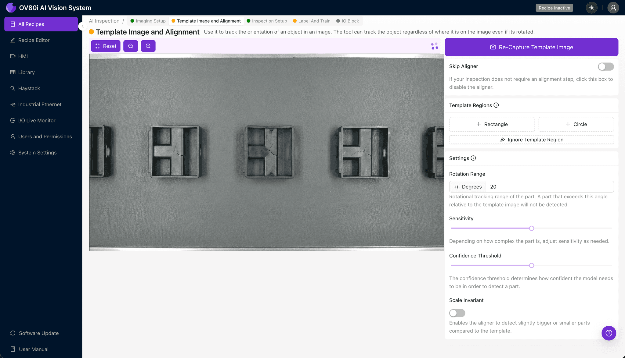
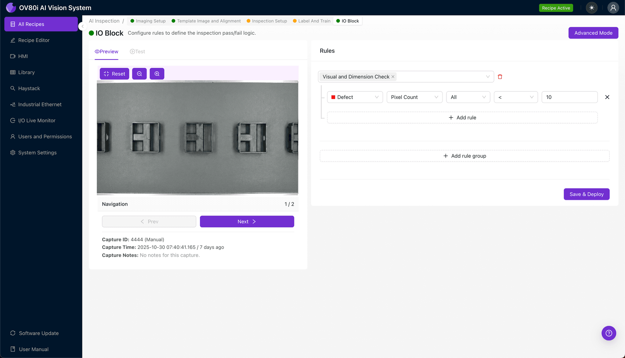
Define your pass/fail logic based on inspection type results. For critical safety components, configure strict rules requiring all bridge zones to pass.
Set up your automation gates to reject any part flagged with bridge defects, routing failures to quarantine bins for engineering review. This ensures no cracked connector reaches your customer.
Key Outcomes & ROI
Implementing AI-powered bridge crack inspection delivers measurable business impact:
- Reduced scrap and rework costs — Catch defects immediately at the source rather than discovering failures downstream or at customer sites
- Higher throughput with 100% inspection — Eliminate sampling bottlenecks while inspecting every single part at full line speed
- Compliance and traceability documentation — Automatically log inspection images and results for audit trails, customer requirements, and regulatory compliance
- Process improvement insights — Identify defect trends by shift, machine, or material lot to drive root cause analysis and continuous improvement
Eliminate Bridge Crack Escapes Today
Stop relying on manual inspection for critical connector components. Deploy Overview.ai to catch cracked bridges instantly at full production speed.