Stiffener Bracket with Non-Planar Mounting Points: A Complete Visual Inspection Walkthrough
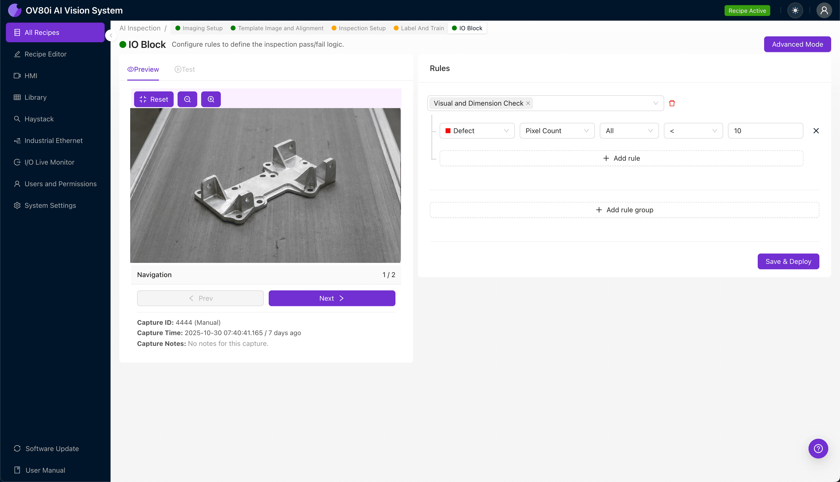
"Stiffener brackets with non-planar mounting points create inspection blind spots that lead to assembly failures. Overview.ai's machine vision platform delivers consistent, objective inspection at full line speed—catching angular deviations, weld defects, and surface cracks that human inspectors miss."
The Problem: Why Traditional Inspection Falls Short
Stiffener brackets with non-planar mounting points present unique quality control challenges in aerospace, automotive, and structural manufacturing. These complex geometries—where mounting surfaces exist at multiple angles and planes—create inspection blind spots that can lead to catastrophic assembly failures downstream.
Common Defects in Stiffener Brackets with Non-Planar Mounting Points
- Angular deviation at mounting surfaces exceeding tolerance specifications
- Weld porosity or undercut at joints between the bracket body and angled flanges
- Surface cracks propagating from stress concentration points near plane transitions
- Incomplete machining on recessed or shadowed mounting faces
- Burr formation along edges where multiple planes intersect
- Hole misalignment or positional drift across non-coplanar mounting surfaces
Human inspectors struggle with these components because the multi-angled surfaces require constant repositioning and refocusing. Inspector fatigue compounds this challenge—studies show detection accuracy drops by up to 20% after just two hours of repetitive visual inspection on complex geometries.
The Solution: Machine Vision + Deep Learning
Machine vision systems eliminate the variability inherent in manual inspection by capturing every bracket with identical lighting, positioning, and analysis parameters. Deep learning models excel at detecting subtle defects across complex, non-planar surfaces because they learn from thousands of labeled examples rather than relying on rigid, rule-based programming.
Overview.ai's approach delivers consistent, objective inspection at full line speed—every single part, every single time. The system doesn't get tired, doesn't have "off days," and maintains the same detection sensitivity on part 10,000 as it did on part 1.
Step 1: Imaging Setup
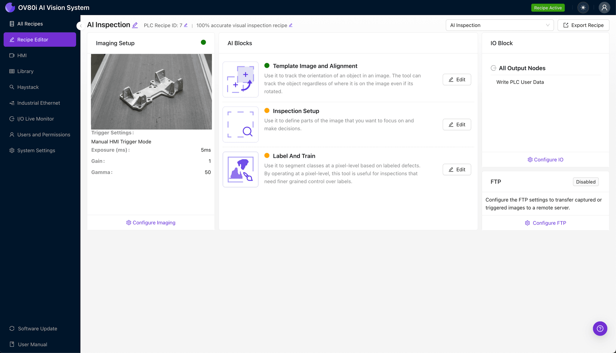
Position the stiffener bracket under the OV80i camera system, ensuring all critical mounting planes are visible within the field of view. For brackets with extreme angular variation, consider a multi-camera configuration or rotary fixture to capture all surfaces.
Navigate to "Configure Imaging" in the Overview interface. Adjust Camera Settings including exposure time and gain to ensure consistent illumination across both the primary bracket body and the angled mounting faces—shadowed areas may require longer exposure or supplemental lighting.
Click "Save" to lock in your imaging parameters.
Step 2: Image Alignment
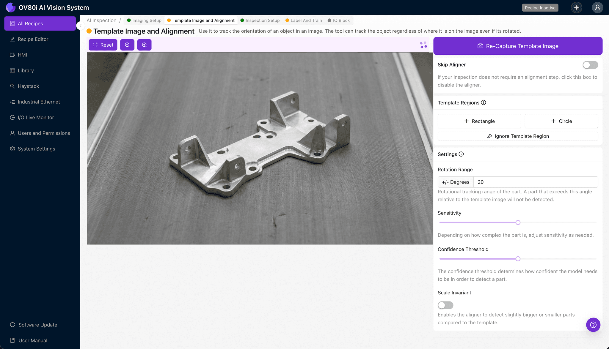
Navigate to "Template Image" and capture a high-quality reference image of a known-good stiffener bracket. This template serves as the alignment anchor for all subsequent inspections.
Click "+ Rectangle" to add a region around the main bracket body, excluding any fixtures or background elements. Set "Rotation Range" to 20 degrees to accommodate part-to-part variation in how brackets are presented to the camera.
Step 3: Inspection Region Selection
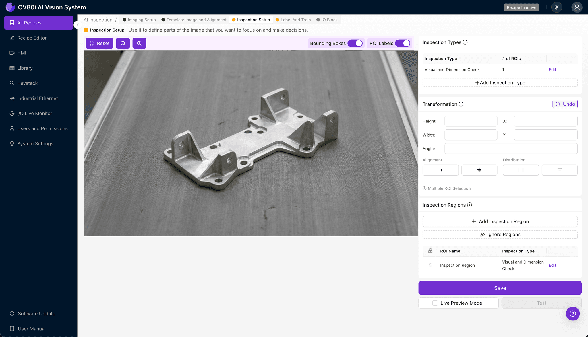
Navigate to "Inspection Setup" to define the specific areas requiring defect detection. Rename your "Inspection Types" with descriptive labels such as "Primary Mounting Surface," "Angular Flange Weld Zone," and "Hole Position Array."
Click "+ Add Inspection Region" for each critical area. Resize the yellow bounding box to cover each non-planar mounting point, weld joint, and machined surface individually—separate regions allow for targeted sensitivity tuning later.
Click "Save" after defining all inspection zones.
Step 4: Labeling Data
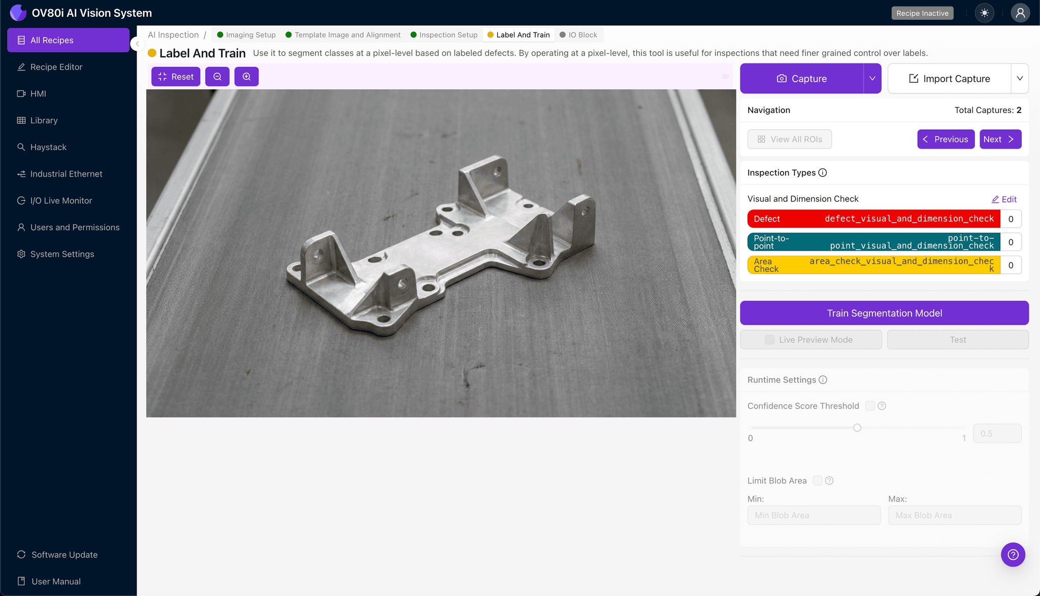
Overview.ai uses a human-in-the-loop process to train its deep learning models on your specific bracket configuration. Production images flow into the labeling queue, where quality engineers classify each as Good or Bad.
Include representative samples across the full range of acceptable variation, not just "perfect" parts. Critically, incorporate known failure modes—angular deviations, weld defects, surface cracks—so the model learns exactly what reject conditions look like on your specific stiffener brackets.
Step 5: Creating Rules
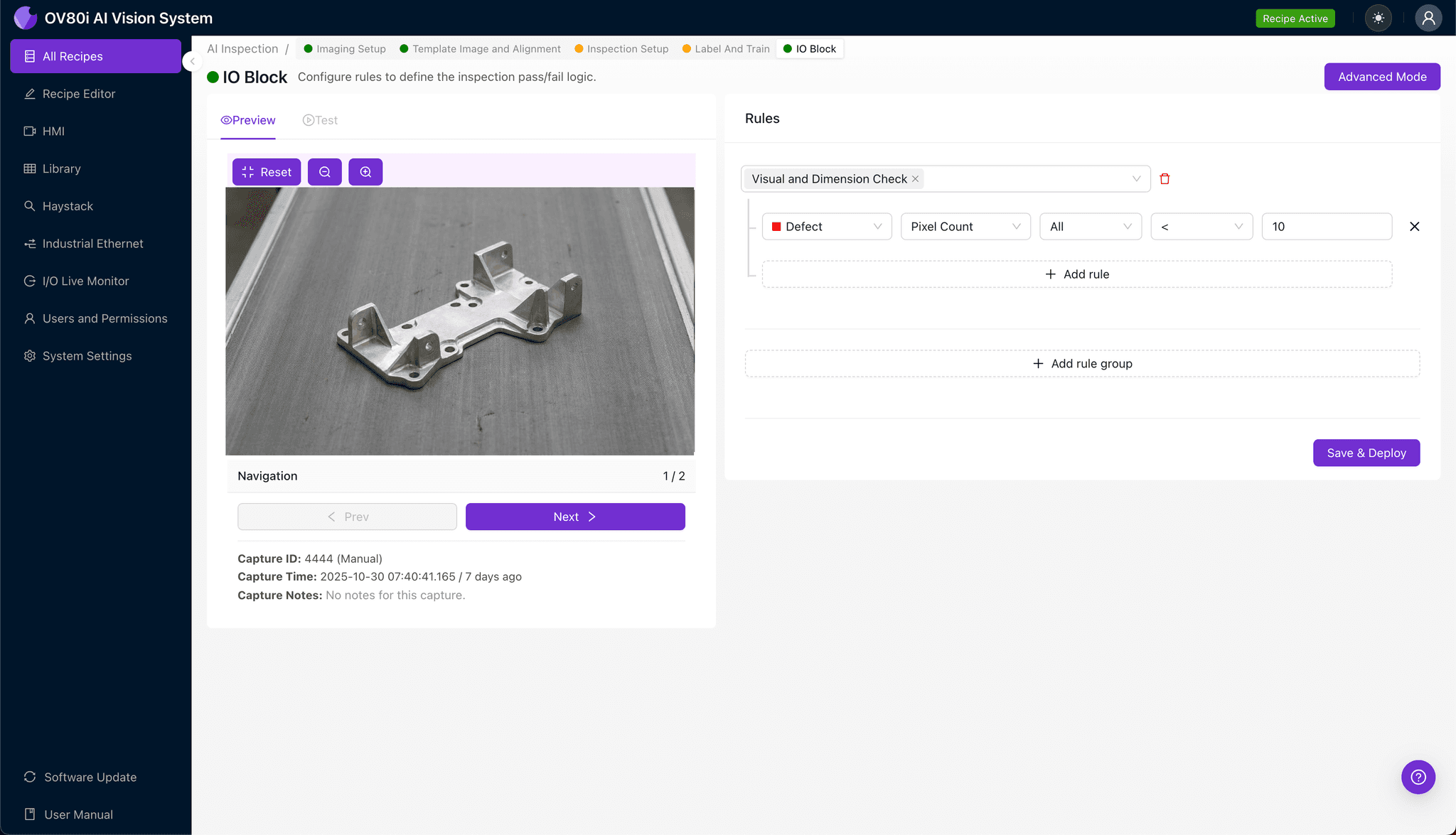
Configure pass/fail logic based on your defined Inspection Types and quality requirements. For example, set rules that reject any bracket showing defects in the "Angular Flange Weld Zone" while allowing minor cosmetic variation in non-critical areas.
These rules gate automated acceptance on the production line, enabling real-time sorting without manual intervention. Parts meeting all criteria proceed to assembly; flagged components route to secondary review or scrap.
Key Outcomes & ROI
Implementing automated visual inspection for stiffener brackets with non-planar mounting points delivers measurable business value:
- Reduced scrap rates by catching defects earlier in the process, before value-added assembly operations
- Higher throughput with 100% inspection at line speed, eliminating the bottleneck of manual sampling
- Enhanced compliance and traceability through automatic image logging of every inspected part with timestamp and disposition
- Process improvement insights from defect trend analysis, enabling root-cause identification and upstream corrections
Conclusion
Stiffener brackets with non-planar mounting points demand inspection precision that manual methods simply cannot deliver consistently. Overview.ai's machine vision platform transforms this quality control challenge into a competitive advantage—ensuring every bracket meets specification while generating actionable data to continuously improve your manufacturing process.
Eliminate Defects Today
Stop relying on manual inspection. Deploy Overview.ai to catch defects instantly.