How to Detect Warped Flanges on Tape-and-Reel Spools with AI-Powered Visual Inspection
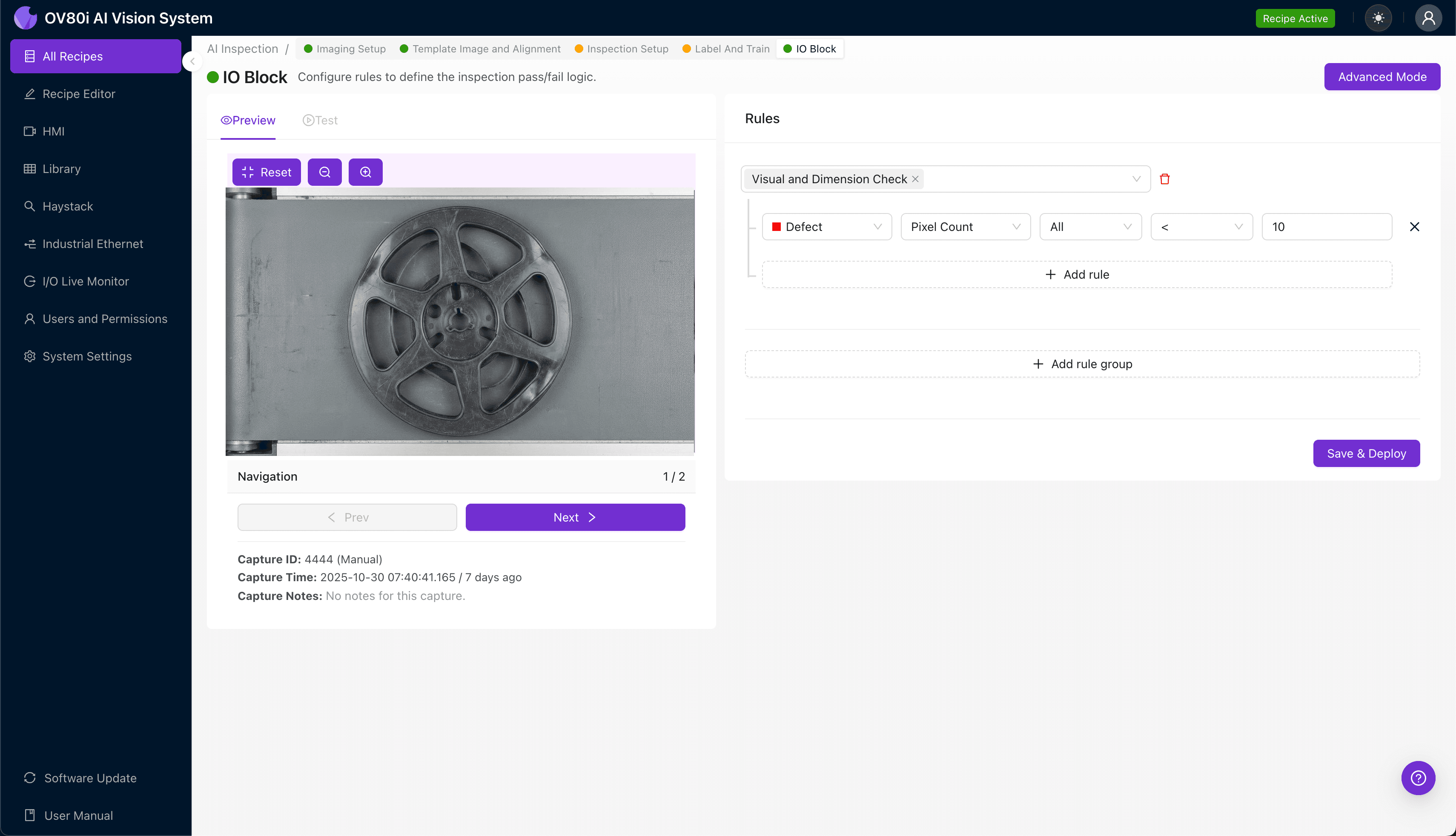
"Warped flanges on tape-and-reel spools cause feeding failures and component damage in SMT assembly lines. AI-powered visual inspection detects deviations as small as 0.1mm at production speed, eliminating the inconsistency of manual inspection."
The Problem: Why Warped Flanges Slip Through Traditional Quality Control
Tape-and-reel spools are the backbone of automated SMT assembly lines, feeding thousands of components per hour into pick-and-place machines. When flanges become warped—even by fractions of a millimeter—the consequences ripple across the entire production process.
Common Defects Found in Tape-and-Reel Spools with Warped Flanges:
- Axial flange deviation — one or both flanges tilted off-perpendicular to the hub axis
- Radial warping — uneven flange surfaces creating "potato chip" distortion patterns
- Hub-to-flange joint separation — gaps or cracks where flanges meet the central core
- Concentricity errors — flanges not centered properly around the hub
- Edge lip deformation — bent or rolled outer edges that interfere with tape tracking
- Thermal stress fractures — micro-cracks from molding or storage temperature variations
Manual inspection of these defects is notoriously unreliable. Inspectors experience fatigue after examining hundreds of spools per shift, and subtle warping under 0.5mm is nearly impossible to catch consistently with the naked eye. The high-speed nature of spool production—often exceeding 60 units per minute—makes 100% human inspection economically unfeasible.
The Solution: Machine Vision + Deep Learning
AI-powered visual inspection eliminates the variability inherent in human quality control. By training deep learning models on thousands of labeled images, the system learns to identify warped flanges with superhuman consistency—detecting deviations as small as 0.1mm across every single unit.
Unlike rule-based machine vision, deep learning adapts to the natural variation in acceptable parts while flagging true defects. This means fewer false rejects and higher confidence in pass/fail decisions.
Overview.ai's Approach
Overview.ai's inspection platform delivers consistent, objective, at-line-speed inspection without slowing production. The system integrates directly into existing conveyor lines, making real-time accept/reject decisions that keep pace with your fastest throughput requirements.
Step 1: Imaging Setup
Position the tape-and-reel spool under the OV80i camera, ensuring the flange face is fully visible and evenly illuminated. Angled lighting works well to accentuate surface warping through shadow variation.
Navigate to "Configure Imaging" in the software interface. Adjust Camera Settings including exposure time and gain until flange edges appear sharp and warping shadows are clearly visible.
Click "Save" to lock in your imaging parameters.
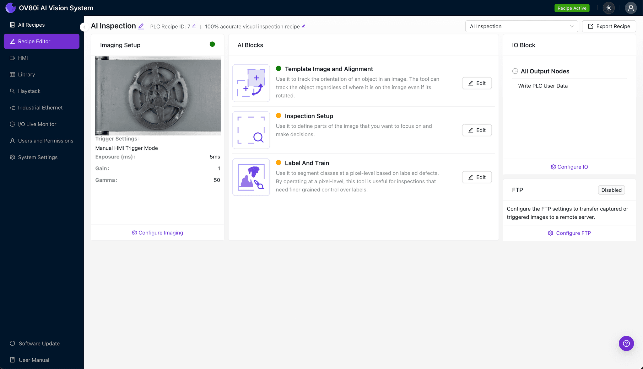
Step 2: Image Alignment
Navigate to the "Template Image" tab and capture a reference image of a known-good spool. This template anchors all future inspections to a consistent baseline.
Click "+ Rectangle" and draw a region around the spool's main body, encompassing both flanges and the central hub.
Set the "Rotation Range" to 20 degrees to accommodate natural variation in how spools enter the inspection zone.
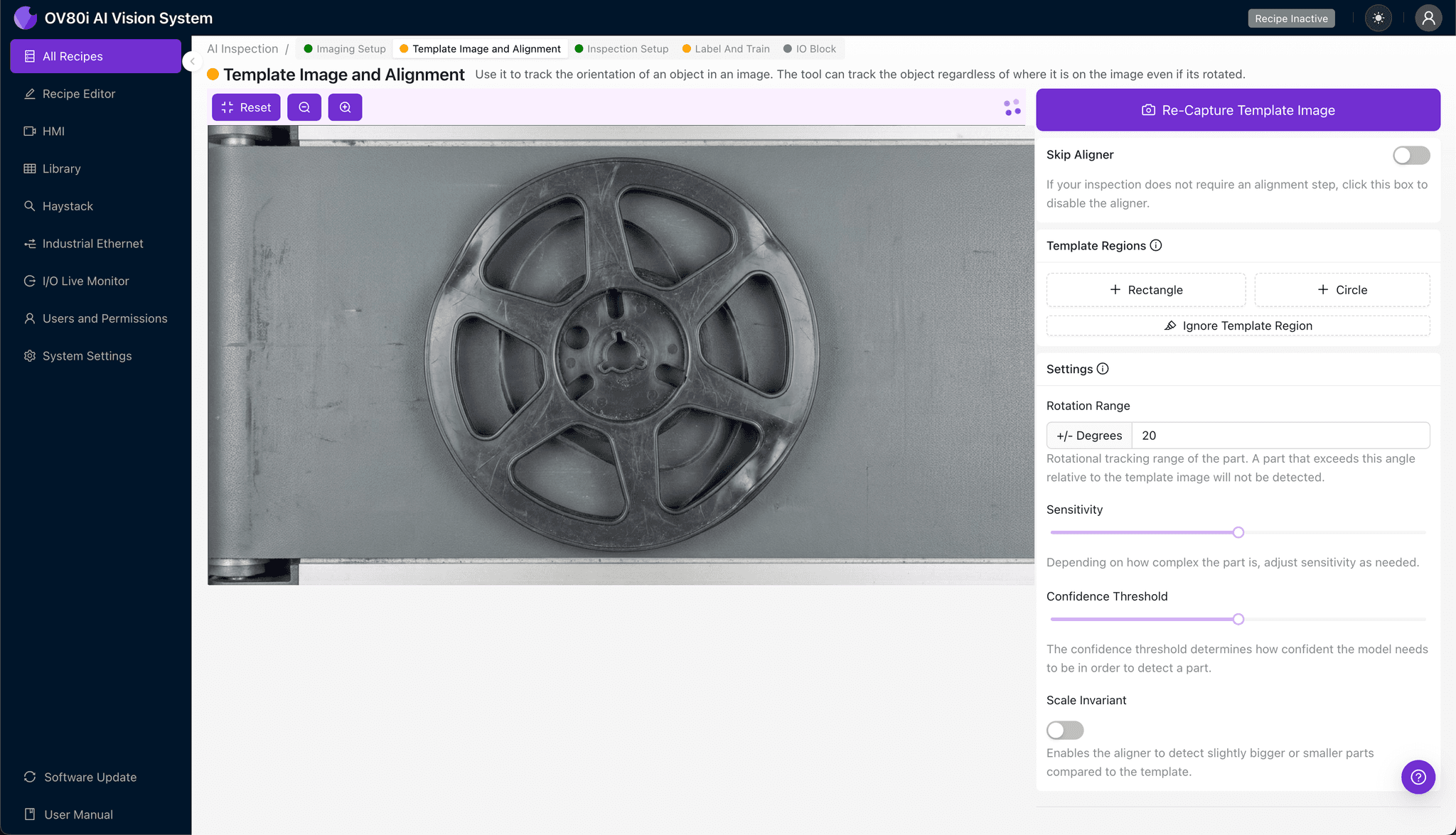
Step 3: Inspection Region Selection
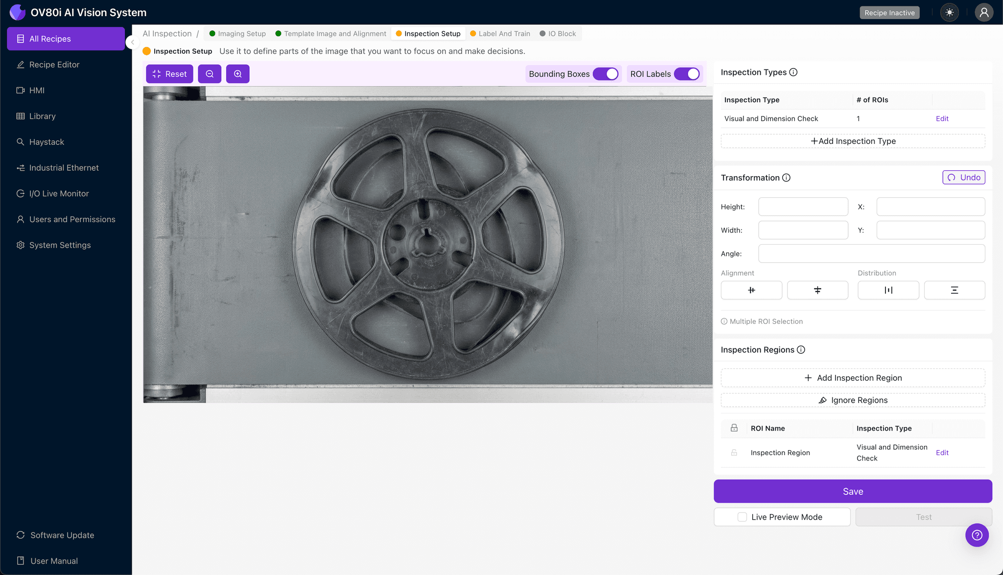
Navigate to "Inspection Setup" to define where the system should look for defects.
Rename your "Inspection Types" to match your quality standards—for example: "Left Flange Warp," "Right Flange Warp," and "Hub Joint Integrity."
Click "+ Add Inspection Region" for each defect type. Resize the yellow bounding box to cover critical areas: flange surfaces, outer edges, and hub connection points.
Click "Save" when all regions are defined.
Step 4: Labeling Data
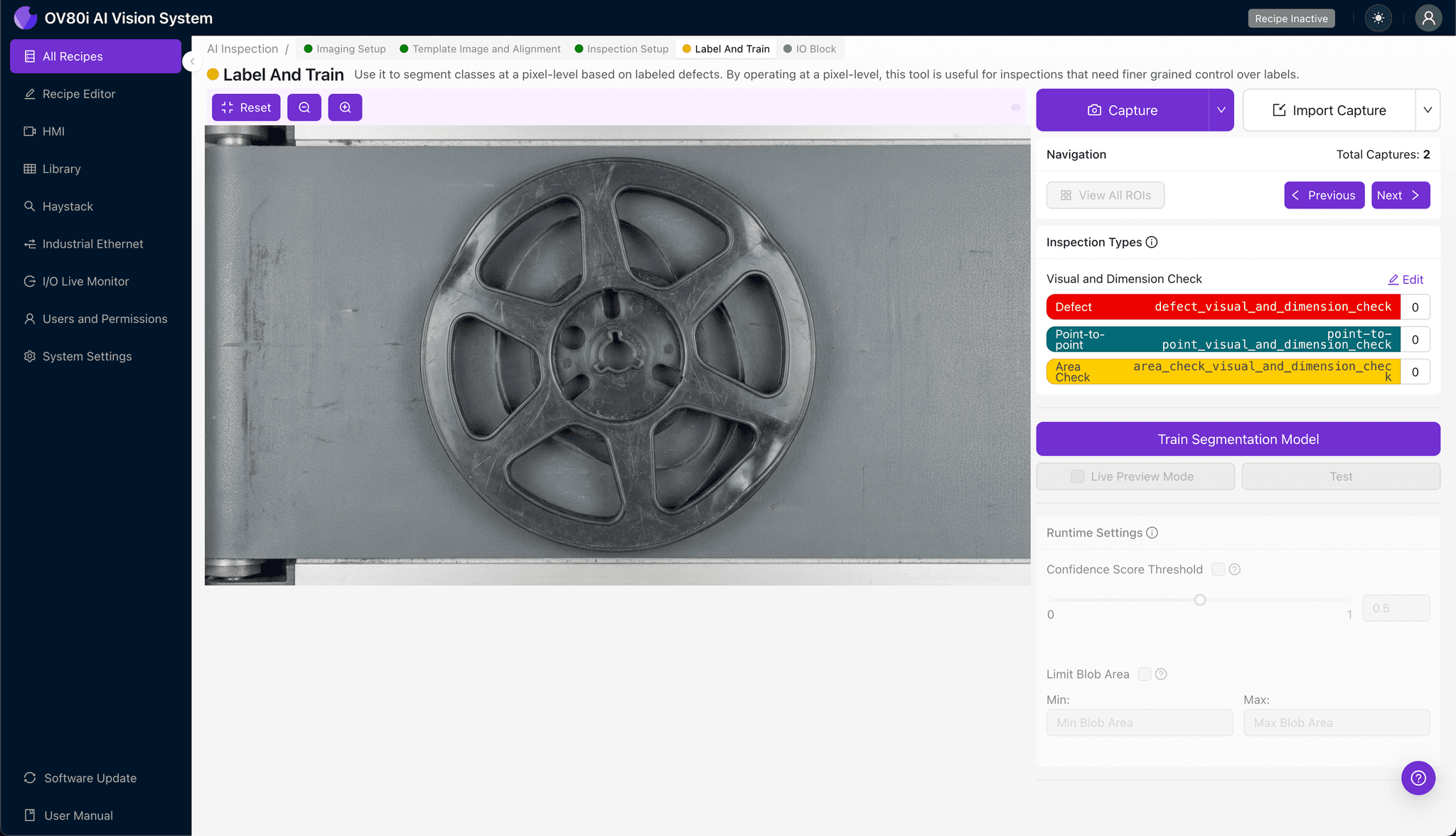
This human-in-the-loop process is where your expertise trains the AI. As production images flow in, you'll review and categorize them.
Label each image as Good (acceptable flange geometry) or Bad (warped, cracked, or deformed). Be thorough—include representative samples of borderline cases and all known failure modes.
The more varied your labeled dataset, the more robust your model becomes at distinguishing subtle warping from acceptable tolerance variation.
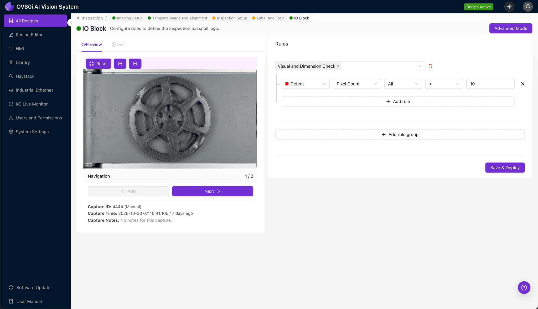
Step 5: Creating Rules
With your trained model ready, navigate to the Rules configuration panel. Set pass/fail logic based on your defined Inspection Types—for example, reject if any flange region scores above your warp threshold.
These rules gate automated acceptance directly on the line. Rejected spools trigger diversion to a quarantine bin or operator review station, ensuring zero defective units reach packaging.
Key Outcomes & ROI
Manufacturers implementing AI-powered warped flange detection report measurable improvements across multiple operational metrics:
- Reduced scrap rates — catch defects before spools enter inventory or ship to customers
- Higher throughput — eliminate inspection bottlenecks with real-time, inline decisions
- Enhanced compliance and traceability — automatically log every inspection with timestamped images for audit trails
- Process improvement insights — identify upstream issues (tooling wear, material batches) causing flange warping trends
Start Inspecting Smarter
Warped flanges don't have to be a hidden quality risk. Deploy Overview.ai to catch defects instantly at production speed.