Detecting Worn Pogo-Pin Tips on TDR Probes: A Machine Vision Walkthrough
"Worn pogo-pin tips on TDR probes cause false readings and damaged DUTs. AI-powered visual inspection detects micron-level wear patterns—flattened crowns, bent shafts, and plating erosion—with repeatable accuracy that manual inspection cannot match."
The Problem: Why Worn Pogo-Pin Tips Slip Past Manual Inspection
Time Domain Reflectometry (TDR) probes rely on precise electrical contact through pogo-pin tips to deliver accurate impedance measurements. When these spring-loaded pins degrade, the consequences ripple through your entire test process—from false readings to damaged DUTs.
Common Defects in TDR Probes with Worn Pogo-Pin Tips:
- Flattened or mushroomed tip crowns — contact surface deformation from repeated compressions
- Bent or misaligned pin shafts — lateral deflection causing inconsistent contact angles
- Contamination buildup — solder residue, flux, or oxidation on contact surfaces
- Plating wear-through — exposed base metal where gold or nickel coating has eroded
- Spring fatigue indicators — reduced travel height or uneven pin extension
- Micro-cracking at the tip — stress fractures from thermal cycling or mechanical overload
Human inspectors struggle to catch these defects consistently. Pin tips measure fractions of a millimeter, and subtle wear patterns become invisible after hours of repetitive inspection. Fatigue compounds the problem—what an inspector catches at 8 AM often slips through at 3 PM.
The Solution: Machine Vision + Deep Learning
AI-powered visual inspection eliminates the variability inherent in manual quality control. Deep learning models trained on thousands of pogo-pin images learn to recognize wear patterns that even experienced technicians miss—detecting micron-level deformation with repeatable accuracy.
Overview.ai's approach delivers consistent, objective inspection at line speed. Whether you're checking 100 probes or 10,000, every single unit receives the same rigorous evaluation without inspector fatigue degrading your escape rate.
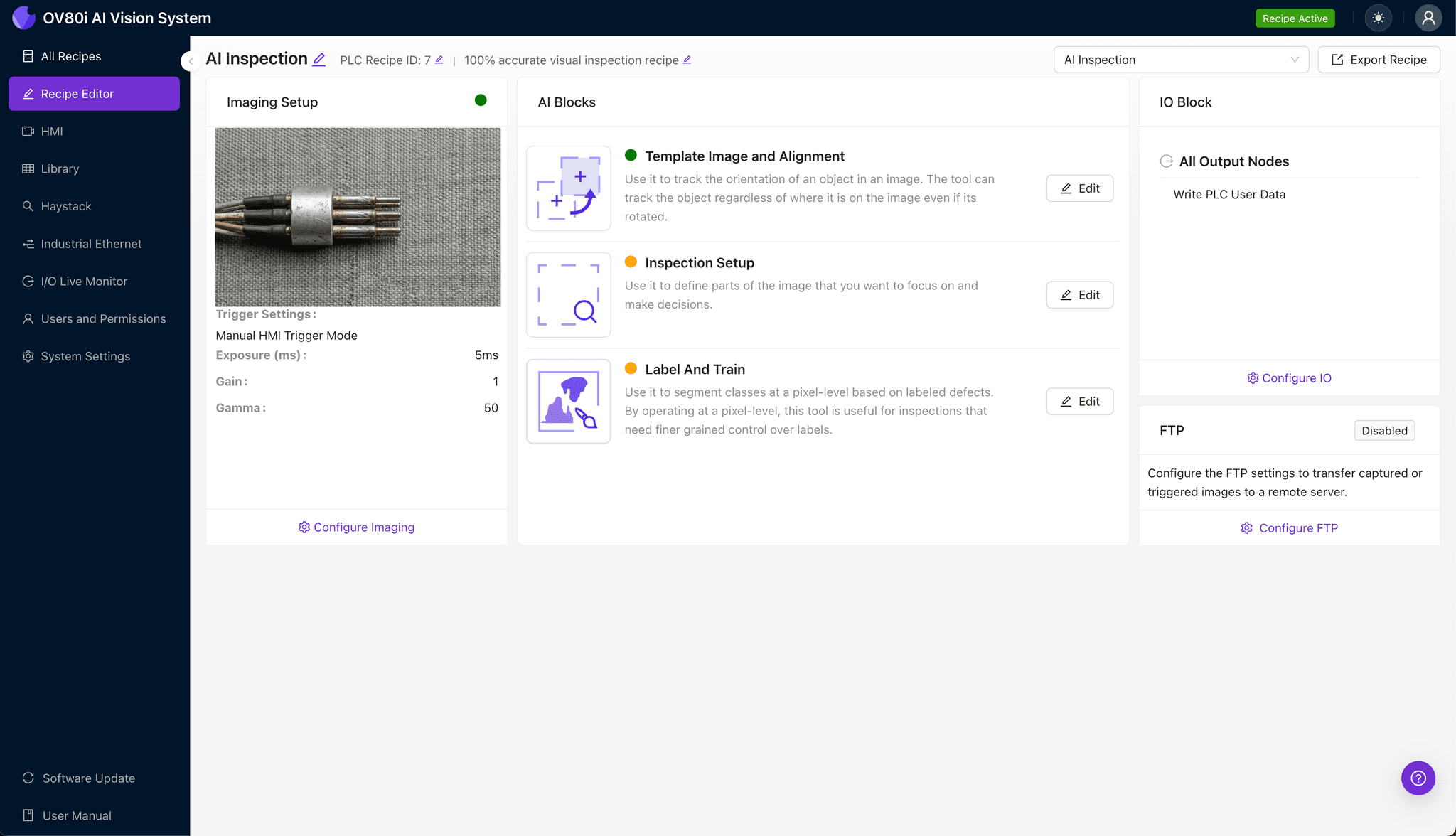
Step 1: Imaging Setup
Position the TDR probe fixture under the OV80i camera, ensuring the pogo-pin tips are oriented perpendicular to the lens for maximum surface detail capture. Proper fixturing is critical—pins should be in their extended position to reveal the full contact crown.
Click "Configure Imaging" to access Camera Settings. Adjust exposure to eliminate glare on reflective gold plating, and fine-tune gain to capture subtle texture differences on worn surfaces.
Click "Save" to lock in your optimized parameters.
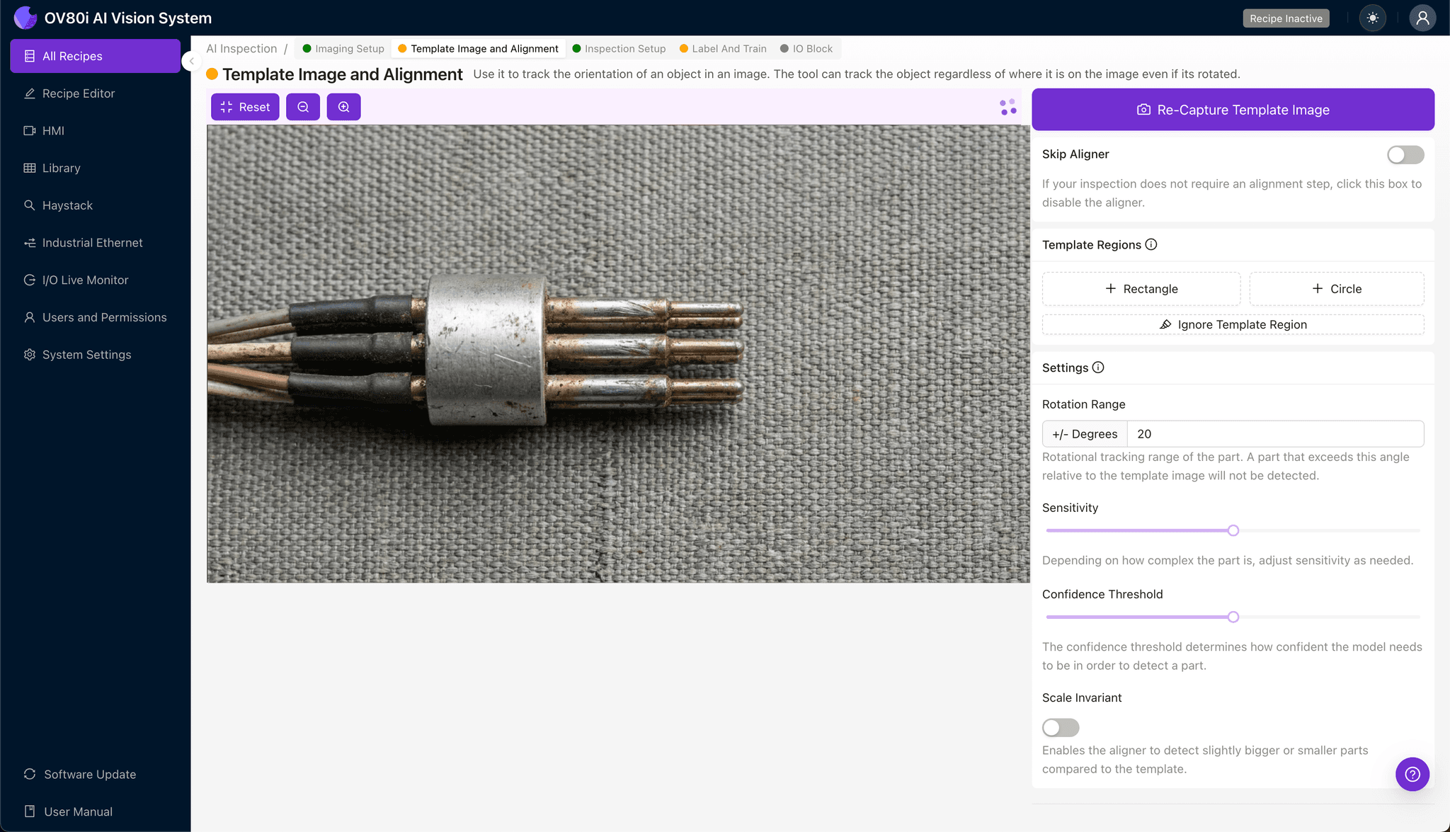
Step 2: Image Alignment
Navigate to "Template Image" and capture a reference image of a known-good probe assembly. This template anchors all future inspections to a consistent baseline.
Click "+ Rectangle" to draw a region around the probe's main body and pin array. Set Rotation Range to 20 degrees to accommodate minor fixture variations during production handling.
Step 3: Inspection Region Selection
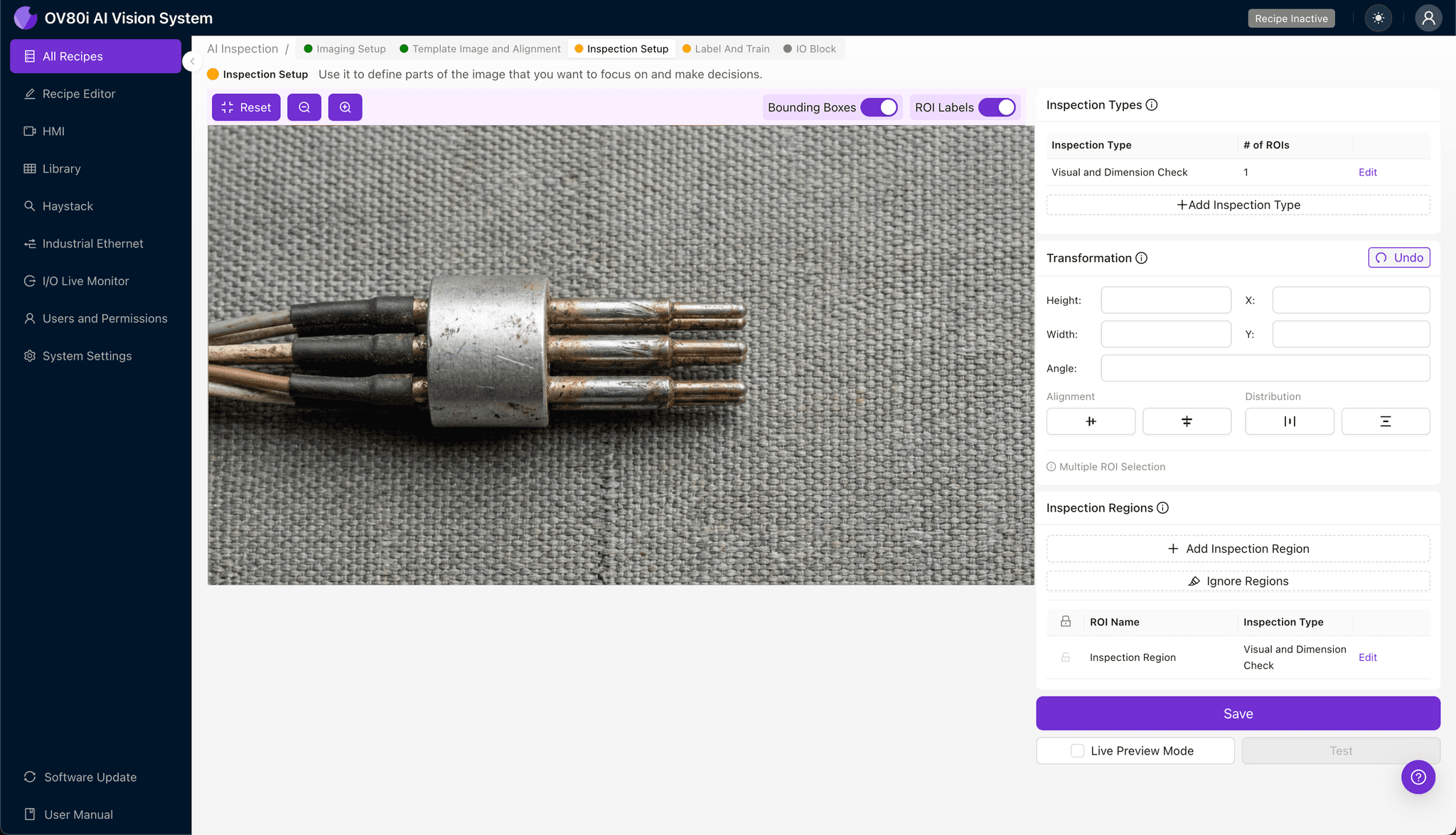
Navigate to "Inspection Setup" to define your critical inspection zones. Rename your "Inspection Types" with descriptive labels—for example, "Tip_Crown_Wear" or "Pin_Alignment."
Click "+ Add Inspection Region" for each defect category. Resize the yellow bounding box to isolate individual pin tips or the full pin array, depending on your inspection strategy.
Click "Save" after configuring all regions.
Step 4: Labeling Data
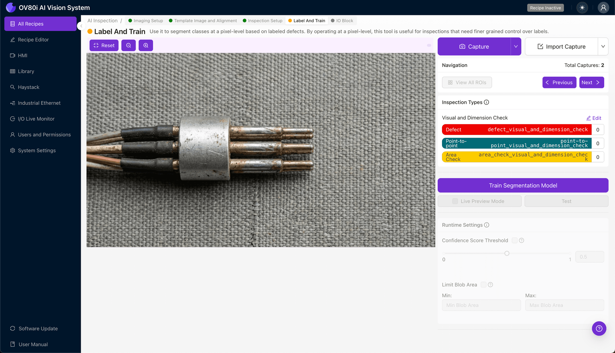
This human-in-the-loop phase teaches the AI what "good" and "bad" actually look like for your specific probes. Quality engineers review captured images and assign labels based on your acceptance criteria.
Label images as Good (acceptable wear levels) versus Bad (out-of-spec degradation). Include representative samples across your full defect library—fresh pins, moderately worn pins, and known failure modes pulled from warranty returns or field complaints.
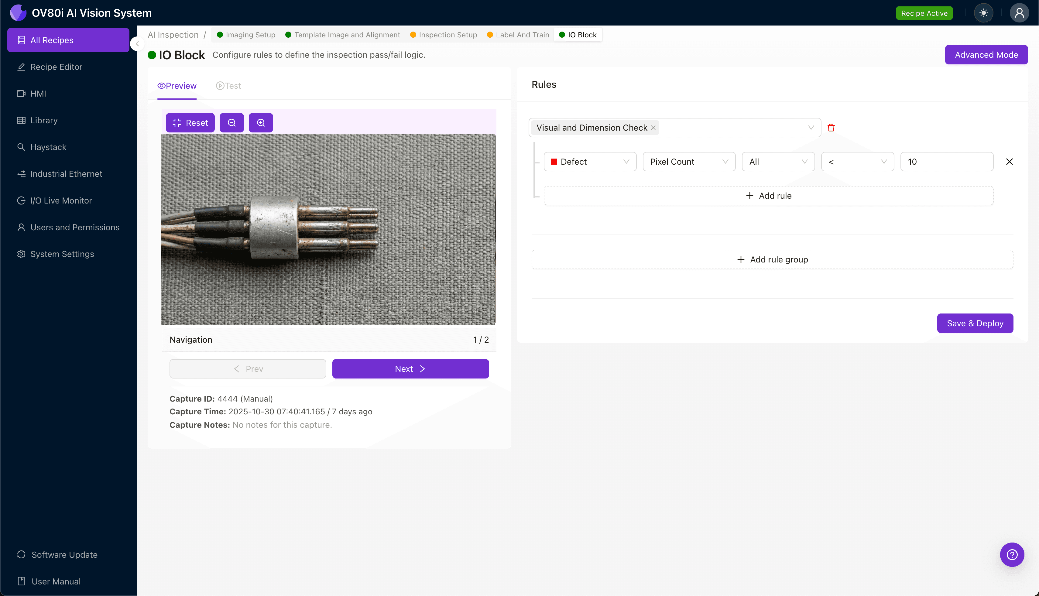
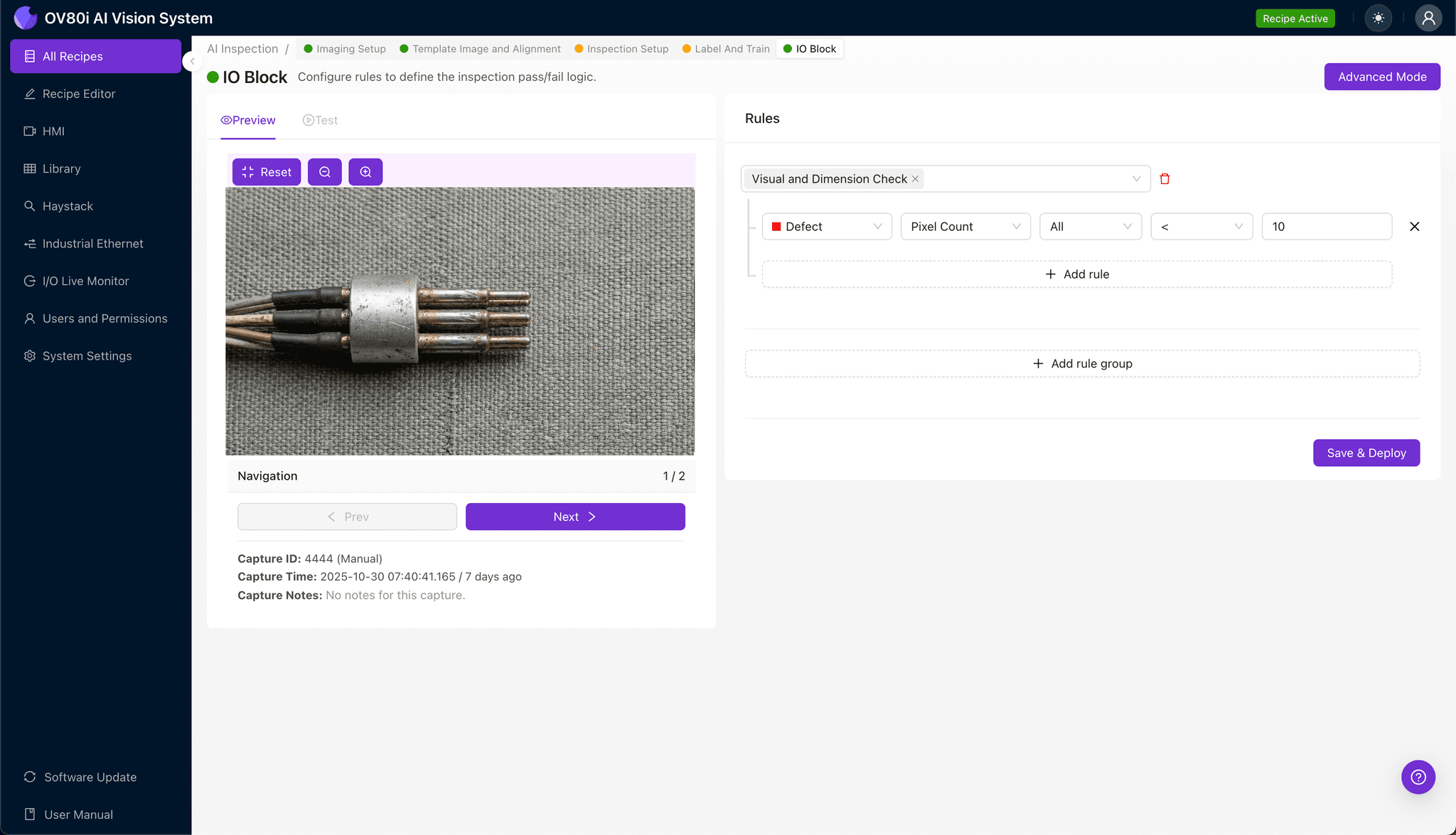
Step 5: Creating Rules
Define your pass/fail logic based on Inspection Type results. For example, flag any probe where "Tip_Crown_Wear" exceeds your trained threshold or where "Pin_Alignment" detects shaft deflection.
Gate automated acceptance on the line—probes that pass proceed to packaging, while flagged units divert to secondary review or scrap. This closed-loop system ensures no worn probe reaches your customer.
Key Outcomes & ROI
Implementing AI-powered inspection for TDR probe pogo-pins delivers measurable business impact:
- Reduced scrap rates — catch wear earlier in the lifecycle, enabling refurbishment before total failure
- Higher throughput — inspect 100% of units at production speed without bottlenecking the line
- Compliance and traceability — maintain complete inspection records with timestamped images for audit readiness
- Process improvement insights — trend data reveals which probe lots degrade faster, informing supplier negotiations and design changes
Conclusion
Worn pogo-pin tips on TDR probes represent a subtle but costly quality risk. Overview.ai's visual inspection platform transforms this challenge into a competitive advantage—delivering the consistency, speed, and accuracy that manual inspection simply cannot match.
Ready to eliminate pogo-pin escapes from your test equipment line? Contact Overview.ai to schedule a proof-of-concept with your actual probe samples.
Eliminate Pogo-Pin Defects Today
Stop relying on manual inspection for critical TDR probe components. Deploy Overview.ai to catch worn tips instantly.