
Part alignment in machine vision: what it actually buys you
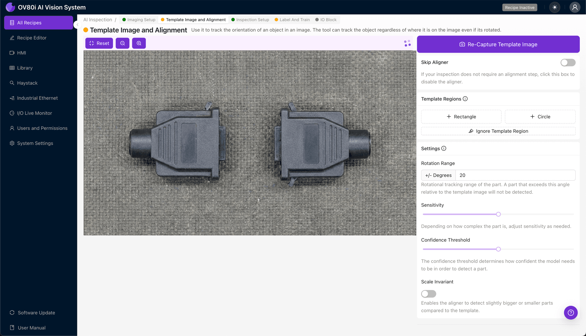
Alignment is the least glamorous stage of an inspection and one of the most consequential, because it decides how much you have to spend on mechanics. A vision system that requires the part in exactly the same place every time is really a specification for a fixture. One that finds the part first can inspect whatever the conveyor delivers.
That trade is the whole subject. Alignment costs cycle time and buys you tolerance to a part that moved. Here is how to price both sides of it.
What the alignment stage does
You give the system a template image of a good part and mark the region that identifies it. On every capture after that, the aligner locates that pattern and works out how the part has translated and rotated relative to the template. Everything downstream then runs in the part's coordinate system rather than the camera's.
The consequence is that your inspection regions travel with the part. A region drawn around a latch stays on the latch when the part arrives 8 mm to the left and rotated 6 degrees. Without alignment that same region would be looking at empty background, and the inspection would report a missing latch on a perfectly good part.
This is why alignment failures and inspection failures are worth counting separately. A part the aligner could not find has not been inspected at all, and a station that quietly passes those is not inspecting a fraction of your production.
Edges or learned features
Classical pattern matching works from edges. It builds a geometric model of the template's edge structure and searches for the arrangement that fits best. It is fast, predictable, and decades proven, and it fails in one specific way: when there are not enough clean edges to work with.
A learned aligner takes the other approach. It learns the visual features of the part from the template rather than relying only on edge geometry, which is what lets it hold onto a part whose edges are unreliable. Three cases where that matters:
Low contrast against the background
A black plastic part on a dark conveyor. The outline exists physically but barely exists in the image, so an edge model has almost nothing to lock onto. Learned features can use surface texture and internal detail instead.
Textured or busy surroundings
A part sitting on woven belt or a machined bed. The background generates more edges than the part does, and an edge matcher can find a convincing false match in the noise.
Specular and variable surfaces
On polished metal the visible edges move with the lighting angle, so the same part presents a different edge map depending on where it sits. Learned features are less tied to that.
When classical still wins
Good contrast, clean geometry, and a part that needs no more than the classical engine already handles. It is faster and there is nothing to gain from switching. Do not pay for capability you do not need.
One practical note if you do switch: the two engines respond to their settings differently, so sensitivity and confidence need re-tuning rather than carrying across. Budget a few minutes for that instead of assuming a like-for-like swap.
The speed modes are a cycle-time decision
Alignment happens before any inspection runs, so whatever it costs comes straight off your cycle-time budget. On the OV80i the aligner offers three modes with published timings, and seeing them as numbers rather than adjectives makes the choice obvious:
| Mode | Approx. time | When to use it |
|---|---|---|
| Fast | ~70 ms | High rate lines where the part is reasonably well presented and you need the milliseconds for the inspection itself. |
| Balanced | ~150 ms | The default, and described in the product as ideal for most applications. Start here and only move if the cycle time or the match rate tells you to. |
| Accurate | ~270 ms | Highest precision. Worth it when downstream regions are tight, when the part is difficult, or when a measurement depends on the alignment being right. |
The span between Fast and Accurate is about 200 ms. On a line at one part per second that is a fifth of your budget, and it is the single largest lever on inspection latency that has nothing to do with the AI models. Worth deciding deliberately rather than leaving on whatever it defaulted to.
Rotation range, and the limit worth knowing
The rotation range setting bounds how far the aligner will look. A part beyond that angle relative to the template is simply not detected, which is a design decision rather than a bug: a narrower search is faster and produces fewer false matches.
Set it from the mechanics rather than optimistically. If the fixture holds the part within a few degrees, a tight range is faster and safer. If parts arrive loose on a belt, you need the range to cover reality or you will be investigating alignment failures that are really a range set too narrow.
The learned engine handles roughly plus or minus 25 degrees. That is a real ceiling and it is better to plan around it than to discover it. Two ways past it when parts can arrive at any orientation: mechanically constrain the presentation so it falls inside the window, or capture more than one template so each covers a slice of the rotation. Neither is exotic, and both are far cheaper to design in than to retrofit.
Scale invariance, and why measurement turns it off
Scale invariance lets the aligner match a part that appears slightly larger or smaller than the template. Useful when part height varies or the camera distance is not perfectly repeatable, because the same part at a different distance images at a different size.
It is also the one setting that interacts with another block, and the interaction is worth understanding rather than fighting. If you are measuring, scale invariance has to be off, and the product enforces this. The reason is straightforward: a measurement converts pixels into millimetres using a fixed scale. An aligner allowed to absorb size changes silently rescales the image, which means the very variation your measurement is trying to detect gets normalised away before the measurement sees it. You would get a beautifully consistent number that no longer reflects the part.
So the rule is simple. Detecting defects on parts whose apparent size wanders: scale invariance on. Reporting a dimension against a tolerance: off, and control the working distance mechanically instead. Our guide to telecentric lenses covers the optical way of removing that same variation.
When to skip alignment entirely
Alignment can be switched off, and on a genuinely well fixtured station you should. If the part is located by a nest or a clamp and arrives in the same place to within a pixel or two, the aligner is spending 70 to 270 ms per capture confirming something the mechanics already guaranteed.
The honest way to decide is to measure rather than assume. Capture a few hundred parts as they normally arrive and look at how much the position actually varies. Two outcomes, both useful: the variation is small and you can drop alignment and reclaim the cycle time, or it is larger than anyone expected, which is worth knowing before you tune inspection regions around an assumption that does not hold.
Skip it when
The part is nested, clamped or indexed into position, presentation repeats to a pixel or two, and the cycle time is tight. The mechanics have already done the job.
Keep it when
Parts arrive loose, on a belt, hand loaded, or in a fixture with real play. Also keep it when the fixture is good today but you would rather the station survive it wearing.
Setting it up, in order
- Capture a template on a good part presented the way production actually presents it, not the way it looks when someone places it carefully by hand.
- Mark the template region on stable features. Larger regions with real detail align better than small ones. Exclude anything that legitimately varies between good parts, otherwise you are asking the aligner to match on the thing that changes.
- Set the rotation range from the mechanics, not from optimism. Measure how much parts actually rotate.
- Start on the balanced mode, then move only if cycle time or match rate gives you a reason.
- Decide scale invariance from the job: on for detection with varying apparent size, off if anything is being measured.
- Re-run the setup against captures you already have. A batch realign over existing images tells you the match rate before the station sees a live part, which is the same discipline as backtesting the inspection itself.
- Decide what a failed alignment does. It is not a pass and it is not the same as a defect. Route it somewhere a human sees it.
That last point is the one most often left to chance. An alignment failure means the part was never inspected, so treating it as a pass puts uninspected product into your good stream. Counting alignment failures separately, and giving the line a signal when the rate climbs, turns a silent gap into an early warning that a fixture is drifting or the lighting has moved. For where this fits in the wider station, see our guide to machine vision systems.
Frequently Asked Questions
What does part alignment do in a vision system?
It locates the part in the image and works out how far it has translated and rotated relative to a template, so every inspection region afterwards is positioned relative to the part rather than to the camera. That is what allows a region drawn around a feature to stay on that feature when the part arrives shifted or rotated. Without it, a moved part causes the inspection to look at the wrong place and report defects that are not there.
What is the difference between pattern matching and a learned aligner?
Classical pattern matching builds a geometric model of the template edges and searches for the best fitting arrangement. It is fast and predictable, and it struggles when there are not enough clean edges. A learned aligner uses visual features of the part rather than edge geometry alone, so it holds on where edges are unreliable: low contrast parts, busy or textured backgrounds, and specular surfaces whose apparent edges move with the lighting. With good contrast and clean geometry, classical remains the faster choice.
How much time does alignment add to a cycle?
On the OV80i the aligner runs in roughly 70 ms in its fast mode, 150 ms balanced, and 270 ms in its most accurate mode. That happens before any inspection model runs, so it comes directly off the cycle-time budget. The 200 ms span between fast and accurate is the largest single lever on inspection latency that has nothing to do with the AI models, which makes it worth setting deliberately rather than leaving at a default.
How much rotation can an aligner handle?
A rotation range is configured explicitly, and a part beyond that angle relative to the template will not be detected. A narrower range is faster and produces fewer false matches, so it should be set from the actual mechanics. The learned engine handles roughly plus or minus 25 degrees. Where parts can arrive at any orientation, either constrain the presentation mechanically so it falls inside that window, or use several templates each covering a slice of the rotation.
Why must scale invariance be off for measurement?
Because a measurement converts pixels to millimetres using a fixed scale. Scale invariance lets the aligner match a part that appears larger or smaller, which effectively rescales the image, so the size variation the measurement is trying to detect gets normalised away before the measurement sees it. The result is a consistent number that no longer describes the part. For detection on parts of varying apparent size, scale invariance is useful; for dimensional measurement it has to be off and the working distance controlled mechanically instead.
Can you run an inspection without alignment?
Yes, and on a well fixtured station you should. If the part is nested or clamped and arrives in the same place to within a pixel or two, alignment spends cycle time confirming what the mechanics already guarantee. The way to decide is to capture a few hundred parts as they normally arrive and measure how much position actually varies, rather than assuming. Either the variation is small and you reclaim the time, or it is larger than expected, which is worth knowing before tuning inspection regions.
See how Overview AI inspects part alignment and fixturing
Send us a photo of your part or defect and a vision engineer will tell you whether Overview can catch it, with most systems deployed on the line in days.
Related Articles
Telecentric Lenses in Machine Vision
The optical way to remove the size variation scale invariance absorbs, and when you need it.
Read More →Escape vs Overkill
Why alignment failures belong in their own column, not folded into the pass rate.
Read More →Global Shutter vs Rolling Shutter
The other geometry problem on a moving part, and how to tell which one you have.
Read More →