Connector metrology
True position and debris, from one capture
Measurement and defect detection are usually two stations. On a contact field they can be the same inspection.
A segmentation pass that locates every contact to sub-pixel precision has already done the work of finding what is sitting on them. Position against a diametric tolerance and foreign object debris come out of the same frame, at line rate.
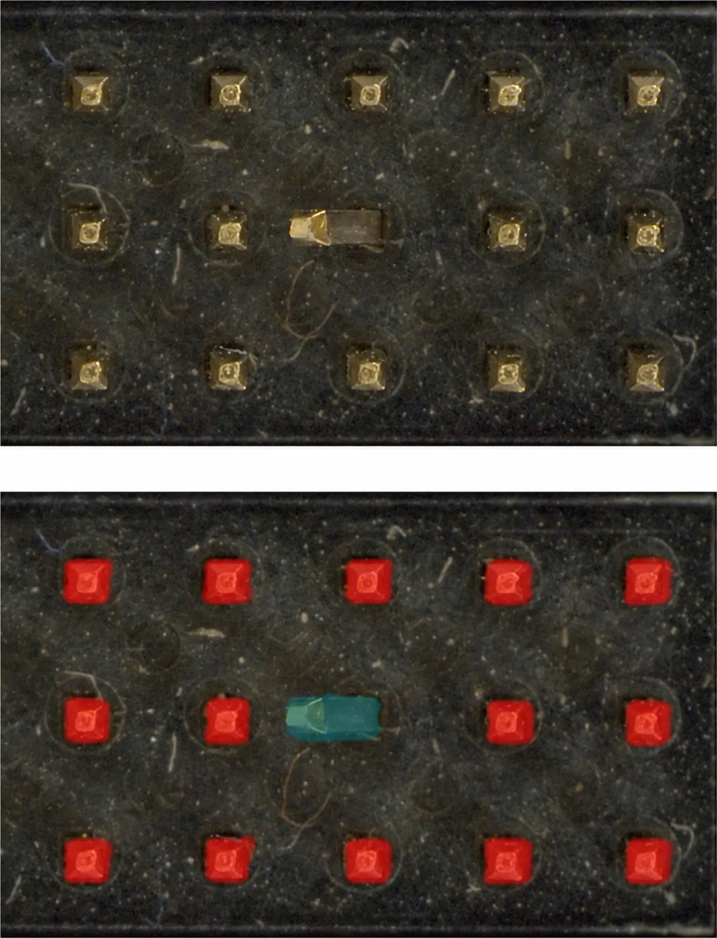
One capture, one segmentation. Every contact carries a mask whose centroid is its measured position, and the contact lying out of its cavity is separated by the same boundary rather than by a second inspection.
What true position means on a contact field
How far a contact sits from where the drawing puts it, reported as a diameter rather than a plus and minus. The tolerance zone is a circle around the nominal centre, so the reported value is twice the radial deviation.
RTP = 2 × √( Δx² + Δy² )
A contact 0.10 mm out in x and 0.10 mm out in y has a radial error of 0.141 mm and a true position of 0.283 mm. Quoting the radial figure halves every number on the report, which is the most common way these results get misread.
How one pass does both jobs
Four steps between the frame and the report
The measurement is not bolted onto the defect check, and the defect check is not bolted onto the measurement. Both are read off the same segmentation of the same image.
Segment every contact
A single inference returns a pixel mask per contact across the whole field, not a crop per pin. Nothing is cropped, windowed or searched for individually, which is why a 160 contact part costs roughly what a 16 contact part costs.
Centroid to sub-pixel
The mask is reduced to a centre by intensity weighted moments rather than by the nearest whole pixel. That is what puts the measurement resolution below the pixel pitch and makes a sensible micron per pixel budget worth paying for.
Fit to the nominal field
A similarity transform registers the measured centres onto the drawing nominals, solving rotation, translation and uniform scale together. Fixture placement leaves the measurement instead of contaminating it.
Report deviation and condition
Position falls out of the residual after the fit. Condition falls out of the mask that produced it. Debris, deformation and a missing contact are all changes in the same boundary the measurement already used.
The alignment problem
Measure the part, not the fixture
A connector never seats identically twice. Measured in raw image coordinates, a part rotated two tenths of a degree reports every outer contact as out of position while the part itself is perfect. That error is placement, and treating it as product is how a capable process starts failing at final inspection.
The fix is a best fit before any deviation is computed. A similarity transform solves rotation, translation and uniform scale across the whole contact field at once, registering the measured centres onto the drawing nominals. The residual left after that fit is the part.
Which datum the fit uses changes every number on the report. A fit to all contacts distributes error evenly and flatters a part with one bad pin. A fit to the datum features named on the drawing reports what the drawing asks for. The two disagree, and only one of them is the specification.
Debris in the same frame
You cannot enumerate contamination
Foreign object debris arrives as metal swarf, solder balls, plating flakes, glove fibre, dust and whatever the previous operation shed. A classifier trained on the list you have seen fails on the first thing you have not, which is why detection is posed as a departure from a clean contact rather than as a set of named classes.
Conductive debris is the expensive one
A metal fragment bridging two contacts is a short in the field, months after it shipped. It is also the hardest to see, because it is metal on metal and the contrast that makes a fibre obvious is not there.
Size follows the optics
The detectable floor is set by microns per pixel and by how many pixels land across the particle, not by the model. Name the smallest particle that matters and the field of view and lens follow from arithmetic.
Position tells you where it came from
Debris recorded against the contact it landed on is process data rather than a reject count. A particle that keeps appearing at the same position in the array points upstream at a specific station.
Proving it
A gauge study, not a demonstration
We ran this as a measurement system analysis on a 160 contact high speed connector with a diametric position tolerance of 0.46 mm. A crossed gauge R&R separated the variation into part to part, repeatability and reproducibility by the ANOVA method, and the result was correlated against a coordinate measuring machine on the same parts.
Against a certified artefact
Every contact on the calibration block measured inside the 0.46 mm zone, with a mean true position error of 0.031 mm. That is the check that the scale and the fit are right before any production part is judged by them.
Against the reference method
Compared with the coordinate measuring machine on the same connectors, 98 percent of contacts agreed within 0.025 mm, with an average difference in reported true position of 7.5 µm. The in-line number and the metrology lab number describe the same part.
At 15 percent of the tolerance band the measurement sits in the conditionally acceptable range under AIAG guidance, where under 10 percent is acceptable and over 30 percent is not. Ten distinct categories is twice the minimum of five, which is what makes the output usable for statistical process control rather than only for disposition.
The hard parts
Four things that decide whether the number is real
Measurement fails differently from detection. A detection either finds the defect or does not. A measurement can be confidently wrong, and a confidently wrong position on a connector is a good part scrapped or a shorted one shipped.
Perspective error is measurement error
Contacts have height. A standard lens sees a pin near the edge of the frame slightly from the side, so its tip and its base do not project to the same centre, and the apparent position shifts with where the part happened to sit. No calibration removes it because it depends on placement. On a diametric tolerance in the tenths of a millimetre, telecentric optics stop being a nicety.
The scale has to be traceable
Microns per pixel is the constant that converts everything. Derive it from a certified artefact rather than from a printed target, record it, and re-check it on a schedule. A scale that has drifted does not produce obviously wrong numbers. It produces plausible ones, which is worse.
Lighting decides where the edge is
A plated contact is curved and specular. Front lighting moves the apparent boundary with the illumination angle, so the same pin measures differently under a lamp that has aged. Geometry that produces a consistent boundary, typically backlighting or a controlled diffuse dome, is what makes the edge repeatable rather than merely visible.
Repeatability before accuracy
A station that is right on average but scatters part to part cannot disposition anything. Repeatability is what the gauge study measures and it is a fair thing to require before the station rejects its first part, not after it rejects the wrong one.
Why bother measuring
A verdict tells you about one part. A number tells you about the process.
Capability, not yield
A distribution of true position values gives you a capability index on the feature. A pass rate gives you the share of parts that happened to clear the line this shift.
Drift before scrap
Position creeping toward the tolerance boundary is visible for hours before anything fails. Tool wear, a loosening fixture and a shifting feed all announce themselves in the mean long before they announce themselves in the reject bin.
Report before you gate
A measurement can run in production and be logged without deciding anything. You collect weeks of real data and set the limit from what the process actually does, rather than switching on a gate and finding out.
How to specify it
- Name the position tolerance from the drawing, and say whether it is diametric. Half the disagreements about whether a system is capable turn out to be a factor of two.
- Name the datum features the fit has to use. A best fit to every contact and a fit to the drawing datums produce different reports on the same part.
- Name the smallest particle that matters, then let the field of view, the lens and the microns per pixel follow. Our optics calculators do that arithmetic for standard and telecentric paths.
- Estimate contact height and seating variation, and check whether the resulting perspective error fits inside the tolerance. If it does not, budget for telecentric optics rather than discovering it during the gauge study.
- Agree the acceptance study up front. A crossed gauge R&R on real parts and a correlation against your reference method, with the thresholds written down before anyone runs it.














Manufacturers running Overview AI in production
Manufacturers running Overview AI in production
FAQ
Frequently asked questions
What is true position on a connector?
True position is how far a contact actually sits from where the drawing says it should, expressed as a diameter rather than a plus and minus. The tolerance zone is a circle around the nominal centre, so the reported value is twice the radial deviation. A contact 0.10 mm out in x and 0.10 mm out in y has a radial error of 0.141 mm and a true position of 0.283 mm. Reporting the radial figure instead of the diametric one halves every number on the report, which is the single most common way these results get misread.
Can one camera measure position and find debris at the same time?
Yes, when the measurement comes from a segmentation model rather than from a separate metrology tool. The model outputs a mask for every contact in the frame. The centroid of that mask, computed to sub-pixel precision, gives position. The shape of the same mask gives condition, because debris sitting on a contact and a deformed contact both change the boundary. One inference produces both answers, so the second check costs cycle time it was already spending.
Why does the part have to be aligned before anything is measured?
Because a part never sits in the fixture the same way twice. Measured in raw image coordinates, a connector rotated a fraction of a degree reports every outer contact as out of position even though the part is perfect. A best fit registers the measured contact field to the nominal field, solving rotation, translation and scale first. What is left after that fit is the part deviation rather than the fixture deviation. Which datum the fit uses changes every number on the report, so it has to match the drawing rather than whatever is convenient in the image.
How do you know the measurement can be trusted?
With a gauge study, the same way any other gauge is qualified. A crossed gauge R&R separates the variation into part to part, repeatability and reproducibility, and reports the measurement error as a share of the tolerance band. AIAG guidance treats under 10 percent as acceptable, 10 to 30 percent as conditionally acceptable depending on the cost and criticality of the application, and over 30 percent as unacceptable. The number of distinct categories should be five or more. Running that study before the station gates production is the difference between a measurement and a demonstration.
Does this replace a CMM?
It replaces the sampling, not the reference. A coordinate measuring machine checks a handful of parts an hour in a controlled environment and stays the arbiter of truth. Vision measures every part at line rate and correlates back to that reference. The useful arrangement is in-line measurement on one hundred percent of production with the CMM retained for periodic correlation, which also gives you a documented, repeatable answer when a customer asks how the in-line number was verified.
What size of debris can be detected?
It follows from the optics rather than from the model. The scale in microns per pixel sets the floor, and a feature needs several pixels across it to be separable from sensor noise and from the texture of the plating underneath. Contrast matters as much as size, since a dark fibre on a gold contact is far easier than a metal fragment on a metal surface. The honest way to specify it is to name the smallest particle that matters, then work backwards to the field of view and lens that put enough pixels on it.
Related
Debris and FOD Detection
Finding foreign object debris inside connector housings and cages before it becomes a field short.
Read more →Dimensional Measurement
Distances, diameters, angles and gaps against a drawing tolerance, and what makes the number trustworthy.
Read more →Bent Pin Inspection
Deformed and displaced contacts on high density connectors, and where position measurement takes over.
Read more →Bring us a drawing
Send the position tolerance, the contact count and the smallest particle you need to catch. You get the optics and an honest answer on whether one station can hold both, before anyone talks to you about hardware.