OV Spark
Trainable part alignment for vision inspection
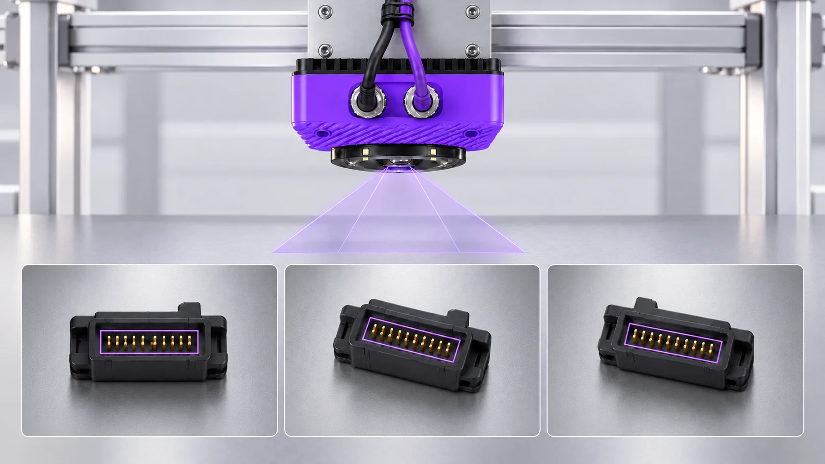
Locate the part first so inspection regions follow the right features as it moves. Trainable alignment gives counting, OCR and other checks a position reference. Your team can refine the aligner with reviewed examples from the onboard Library when the part’s finish or appearance changes.
Ten tools. One camera.
The right part.
In the right place.
Find the part’s position and orientation so downstream inspection regions follow the features you need to check.
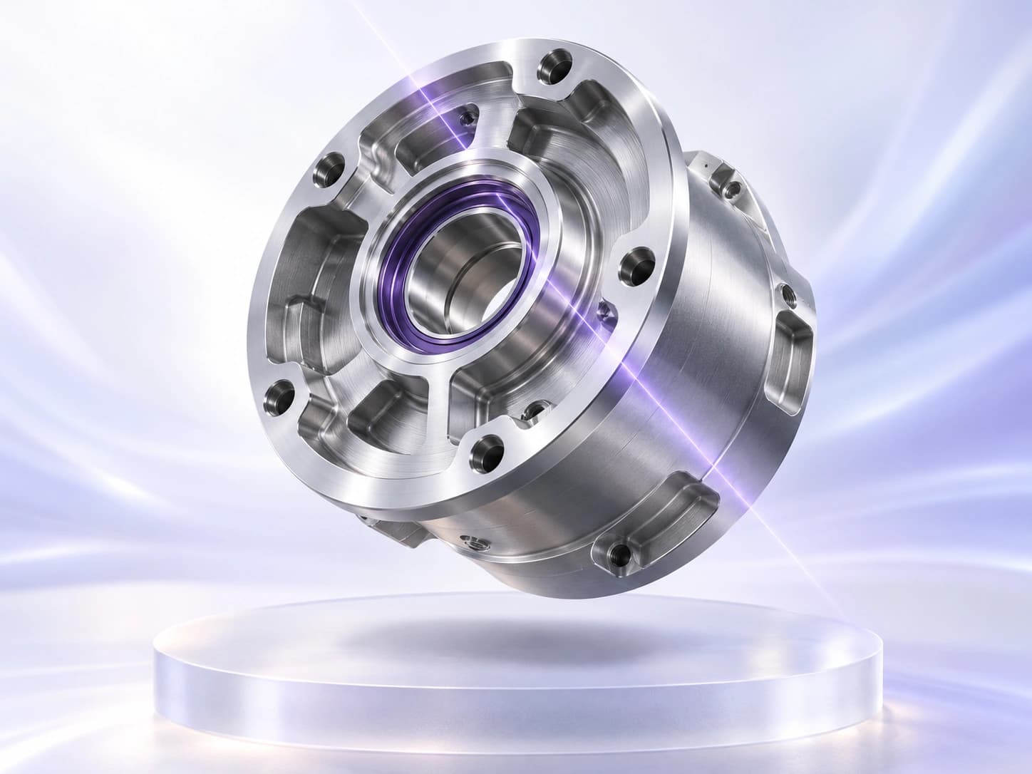
Count visible parts or features and compare the result with your configured target range.
Measure gaps, diameters or distances, then compare them with your limits. Calibrate the image for physical units.
Compare a region with a colour reference and your allowed tolerance to check variants and consistency.
Train on examples of your defined classes, then classify the part or image region for the inspection.
Use the image to identify when the part is in the right position, without an external trigger sensor.
Find the flaws
that matter.
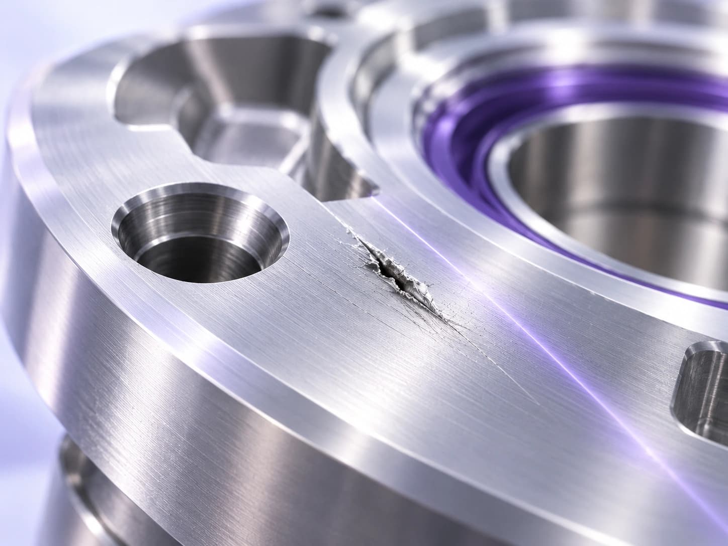
Identify the pixels belonging to a defect. Inspect scratches, coating coverage and weld quality where location and area matter.
Learn from good samples, then flag deviations from that pattern—even when defect examples are scarce.
Read it.
Then verify it.
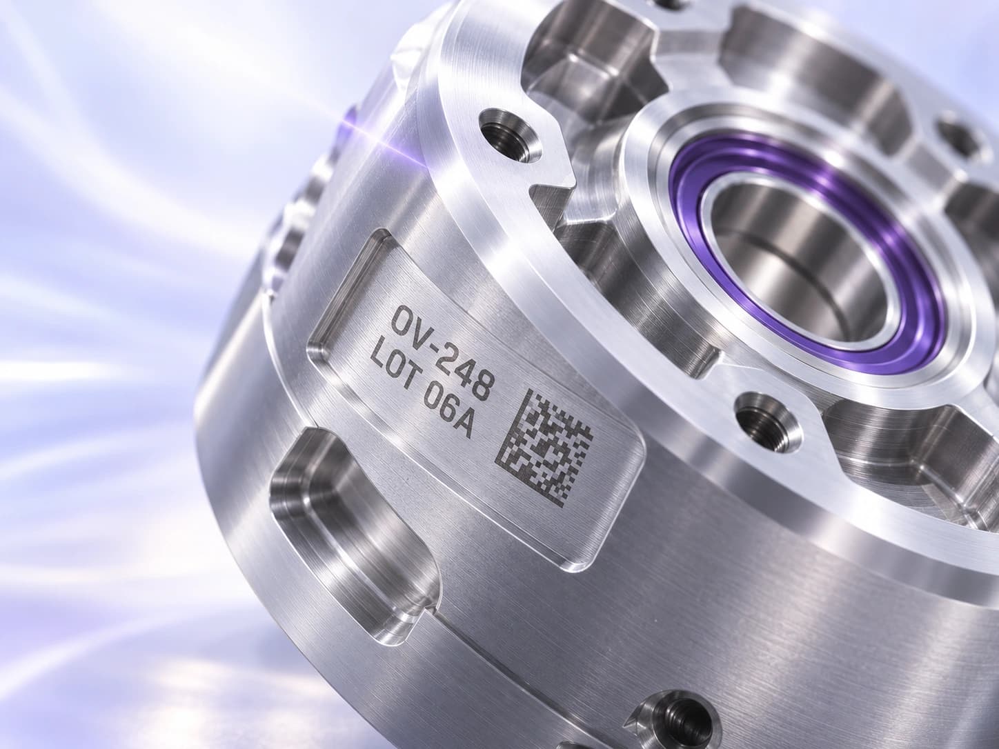
Read one line per OCR region and compare it with the expected string or pattern. Use separate regions for separate lines of lot, date or product codes.
Decode a 1D or 2D barcode, then check its content against the value your inspection expects.
Find a reliable reference on the part
Choose a feature that remains visible across acceptable parts. A housing outline, a mounting feature, or another stable detail can give the inspection a useful reference. Avoid relying entirely on a component whose presence is the thing you need to inspect. If that component is missing, the camera still needs a way to locate the assembly.
The reference should also distinguish the orientations that matter. A symmetrical outline may look the same after the part rotates. If orientation affects assembly acceptance, include a visible feature that tells those poses apart. The image must contain the information needed to make that distinction.
Correct detections with additional examples
Spark supports additional training for its aligner. Review the candidate detections and mark whether each one is correct or misaligned. These annotations teach the aligner which matches to accept and which to reject, using the images already relevant to your application. When a new finish or appearance causes an uncertain location, those examples give you a direct way to refine the tool.
Include normal changes in finish, position, and orientation in the evaluation. Also include empty fixtures and nearby features that might resemble the target. A useful aligner should find the right reference when it is present and report a failed location when it is absent.
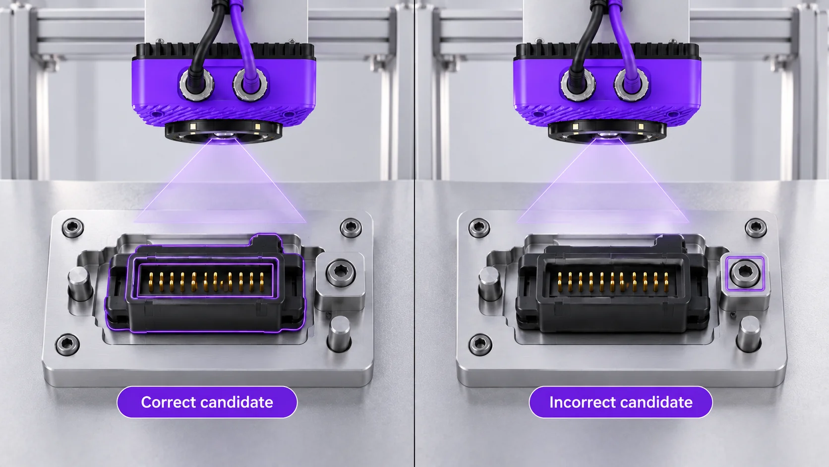
Use alignment before the inspection tools
Once the part is located, inspection regions can follow that reference. A terminal row, clip position, or printed line can move within the image while the relevant check stays with it. That reduces the need to widen a region just to catch positional variation, helping the inspection stay focused on the intended feature. Configure each downstream tool to use the alignment and test the complete sequence.
Keep location and quality decisions distinct. Finding a housing establishes where to inspect it. It does not establish that every component is present or that a code is correct. Those decisions belong to the relevant inspection tools. Define what the recipe should report when alignment fails so an unlocated part cannot be mistaken for a completed inspection.
Evaluate the movement your line actually produces
Collect images from the edges of the expected movement range, not just the center of the fixture. Check rotated parts, normal conveyor wander, and the positions reached during loading. Then inspect the downstream results. A plausible alignment overlay is only useful if the tools still examine the intended features.
Lighting, focus, and the camera view remain important. Alignment cannot restore a feature hidden behind another component, and an out-of-plane tilt may change what is visible. For an application that uses successful alignment to trigger inspection, evaluate trigger timing and repeated detections separately from location accuracy. The test should include the intended line speed and spacing between parts.
Evaluate the complete recipe on the intended model: 1.2 MP Spark or 5 MP Spark Pro. Include exposure, alignment and downstream tools when measuring cycle time; a single tool’s timing does not establish station throughput.
Common questions
- What does part alignment do in a vision inspection?
- It establishes the part location before other checks run. Inspection regions can then be configured relative to that location, helping the system handle expected shifts rather than assuming the part always occupies the same image coordinates.
- How is Spark alignment trained?
- You can provide additional examples by reviewing candidate detections and marking them correct or misaligned. Use examples that reflect the application, then evaluate the result on separate images and on the line.
- Can alignment replace a fixture?
- It may allow more positional variation where the part remains visible and the inspection can follow it. Fixturing may still be needed to control viewing angle, motion, overlap, or depth. Evaluate the mechanical setup and the vision task together.
- Is alignment the same as defect detection?
- No. Alignment finds the reference used by the inspection. Counting, classification, OCR, and other tools evaluate the relevant quality requirements. A successful alignment alone does not mean the part is acceptable.
Show us how your part moves
Bring images or samples across the expected positions and orientations. We can evaluate the reference feature and the checks that need to follow it.
Discuss your alignment task